LANGUAGE
 中文简体
 русский
 Français
 Español
 Português
 عربى

Content
- 1 Why a Complete Wire and Cable Extrusion Line Matters
- 2 Complete Process Configuration
- 2.1 Motorized Pay-Off System
- 2.2 Wire Straightening and Guiding Section
- 2.3 Extrusion Machine and Crosshead
- 2.4 Electrical Control and Operation Cabinet
- 2.5 Diameter Measurement System
- 2.6 Cooling Tanks
- 2.7 Ink Printing Machine
- 2.8 Dual-Wheel Take-Up and Caterpillar Haul-Off
- 2.9 Storage and Tension Control Racks
- 2.10 Dual-Axis Take-Up Machine
- 3 Extrusion Technology for Different Polymer Materials
- 4 Screw and Barrel Design
- 5 Temperature Control and Melt Stability
- 6 Production Models and Capacity Range
- 7 Closed-Loop Diameter Control
- 8 Haul-Off Tension and Conductor Protection
- 9 Manufacturing Strengths and Engineering Approach
- 10 Advantages Over Conventional and Disconnected Equipment
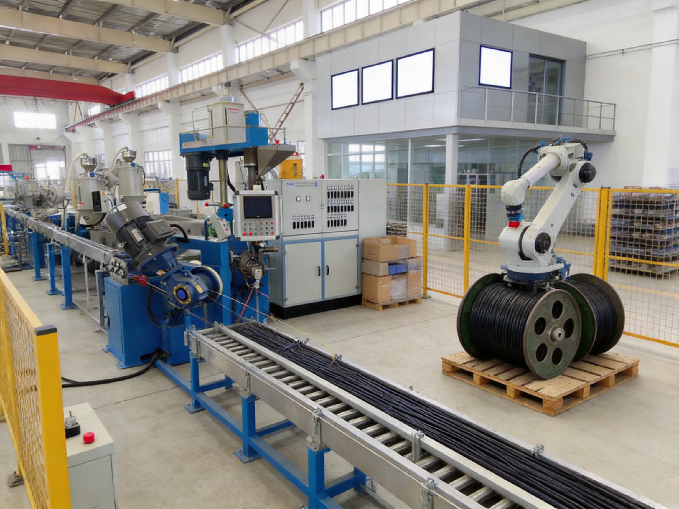
- 11 Automatic Coiling and Robotic Palletizing Integration
- 12 Retrofitting Existing Cable Lines
- 13 Quality Control During Cable Production
- 14 Maintenance Recommendations
- 15 Energy Efficiency and Operational Economy
- 16 Applications
- 17 How to Select the Correct Model
- 18 Frequently Asked Questions
- 18.1 What is a wire and cable extrusion line used for?
- 18.2 Which materials can the equipment process?
- 18.3 Why are different screw designs needed?
- 18.4 Can the line control cable diameter automatically?
- 18.5 Does an outer diameter gauge measure insulation eccentricity?
- 18.6 What is the purpose of the cooling tanks?
- 18.7 How does haul-off speed affect cable quality?
- 18.8 Can the system produce both small and large cables?
- 18.9 Can automatic coiling be added later?
- 18.10 Is retrofitting possible for an older cable line?
- 18.11 What information should be provided when requesting a quotation?
- 19 Conclusion
- 20 References
- 21 Product: Wire And Cable Extrusion Line
Wire and cable manufacturing requires more than an extruder with a motor and die. To achieve stable insulation thickness, reliable electrical performance, consistent surface quality, and high production efficiency, manufacturers need a coordinated production system in which feeding, extrusion, cooling, diameter measurement, printing, hauling, tension control, winding, and take-up operations work together. A modern wire and cable extrusion line provides this complete manufacturing platform.
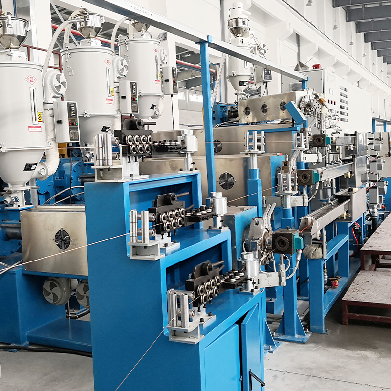
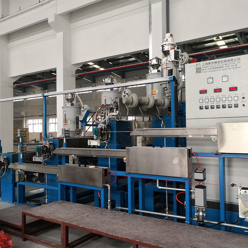
Designed for the continuous production of insulated wires and sheathed cables, the line integrates multiple machines into one controlled process. Conductors enter through a motorized pay-off system, pass through straightening and guiding equipment, receive a precisely controlled polymer layer in the extrusion machine, and then move through cooling, measurement, printing, hauling, storage, and take-up stages. This integrated structure reduces manual handling and allows production teams to maintain repeatable operating conditions over long production runs.
Shanghai Yessjet Precise Machinery Co., Ltd. supplies customized wire and cable machinery and complete cable production line solutions for different conductor sizes, polymer materials, production speeds, and finished cable diameters. Its equipment is configured for materials such as PVC, LDPE, LSZH, Teflon, nylon, and other thermoplastic compounds. The company combines mechanical manufacturing, extrusion technology, electrical control, process engineering, and automation integration to create production lines suitable for both standard wire products and specialized cable applications.
Why a Complete Wire and Cable Extrusion Line Matters
Many cable production problems do not originate in one machine alone. A diameter fluctuation may be caused by unstable extrusion output, incorrect haul-off speed, poor conductor tension, inadequate cooling, or delayed feedback from the measuring system. Surface defects may result from an unsuitable screw design, incorrect temperature settings, contamination, or excessive belt pressure in the caterpillar haul-off. If each section of a production line operates independently, these problems are difficult to identify and correct.
A complete extrusion line solves this problem by coordinating all sections through a central control system. The extruder, pay-off, haul-off, cooling tanks, diameter gauge, printing unit, storage rack, tension system, and take-up machine operate according to a defined process sequence. Operators can adjust key parameters from a central electrical cabinet or touchscreen interface, while sensors and control devices provide real-time information about temperature, line speed, diameter, tension, and machine status.
This integrated approach delivers several important benefits:
- Stable insulation and sheath thickness over long production runs.
- Better synchronization between extrusion output and line speed.
- Reduced conductor stretching caused by excessive tension.
- Faster changeovers between different cable specifications.
- Lower dependence on manual adjustment.
- Improved traceability through programmable recipes and production data.
- Higher productivity with fewer stoppages and less material waste.
- More convenient integration with automatic coiling and robotic palletizing equipment.
Compared with a collection of unrelated machines, a coordinated extrusion line offers better process visibility and more predictable production results. This is particularly important when manufacturers supply cables to customers that require strict dimensional tolerances, stable electrical properties, and repeatable batch quality.
Complete Process Configuration
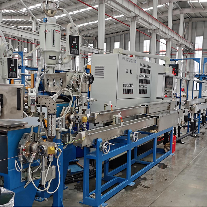
A typical wire and cable extrusion line consists of several connected sections. The exact configuration depends on the conductor diameter, insulation material, finished product size, line speed, and packaging requirements. The main components supplied in a complete system include the following.
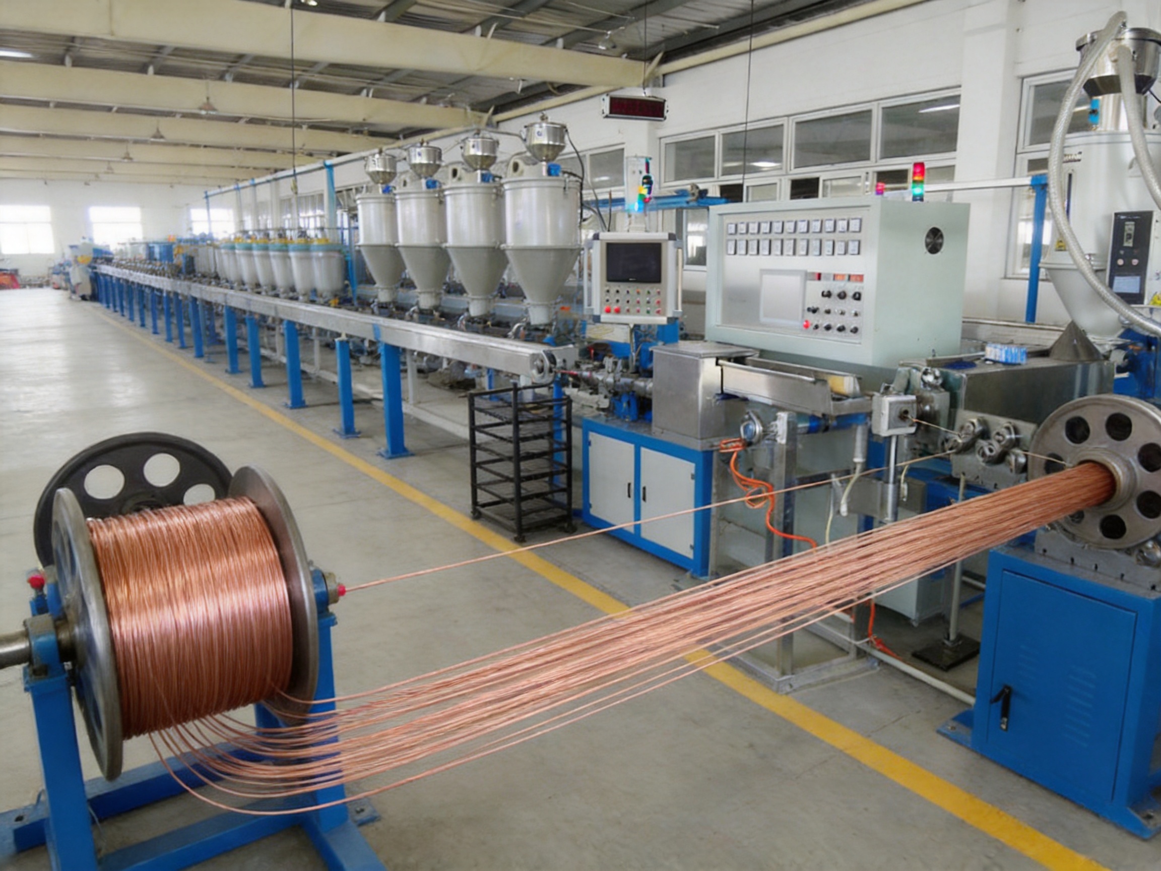
Motorized Pay-Off System
The pay-off system releases copper, aluminum, stranded, or other conductors from a coil or reel at a controlled speed. A stable pay-off is essential because changes in incoming conductor tension can affect the final insulation thickness and cable concentricity. Motorized systems provide controlled release rather than relying only on passive reel rotation.
For high-speed production, the pay-off can be combined with dancer feedback, braking control, wire guiding, and automatic tension adjustment. These features help prevent sudden tension peaks, conductor slack, or uncontrolled acceleration during startup. A correctly selected pay-off also reduces the risk of conductor scratches before the insulation process begins.
Wire Straightening and Guiding Section
Conductors may develop bends or irregularities during stranding, storage, or previous processing. The straightening stand guides the conductor into a stable path before it reaches the crosshead. This improves the position of the conductor inside the insulation layer and helps maintain consistent eccentricity.
Accurate guiding is especially important for small-diameter wires, high-speed production, and cables with tight wall thickness tolerances. The guiding system must be aligned with the extrusion crosshead, cooling trough, and haul-off so that the conductor follows the centerline of the complete machine.
Extrusion Machine and Crosshead
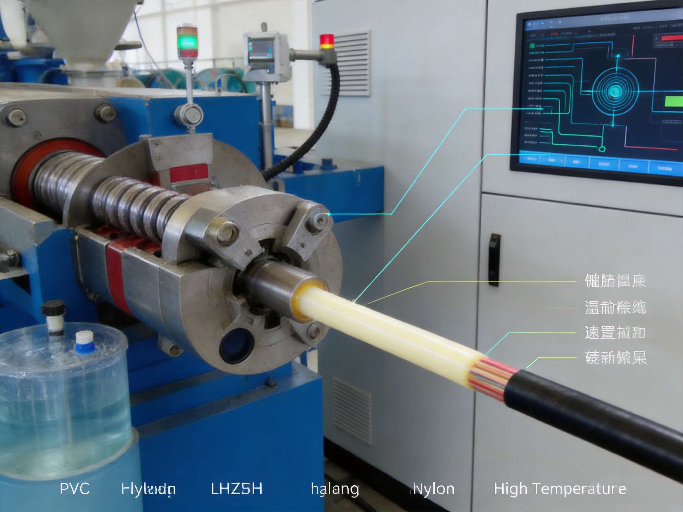
The extrusion machine melts and meters the polymer compound before delivering it to the crosshead. Inside the crosshead, the molten material is formed around the moving conductor. The quality of this section directly affects the finished cable’s outer diameter, insulation thickness, surface appearance, and electrical performance.
The supplied extruders use imported barrel and screw components from Taiwan and are configured for high extrusion capacity. Different polymer families can be processed using appropriate barrel, screw, temperature, and tooling configurations. PVC, PE, LSZH, Teflon, nylon, and related materials do not behave identically during melting and flow, so the screw design and processing conditions must be selected according to the compound.
Electrical Control and Operation Cabinet
The main electrical control cabinet coordinates the line. A programmable logic controller manages startup sequences, interlocks, alarm conditions, speed synchronization, temperature control, and communication with measurement equipment. Operators can monitor machine status and adjust process parameters through the operating interface.
PLC control provides a significant advantage over relay-based or manually adjusted systems. A recipe can store extrusion speed, haul-off speed, temperature setpoints, take-up conditions, and other product-specific parameters. When the same cable specification is produced again, operators can recall the recipe and reduce setup variation.
Diameter Measurement System
An outer diameter measuring instrument continuously checks the finished wire or cable. The measurement signal can be used for monitoring, alarm generation, or closed-loop correction. If the diameter moves away from the target value, the control system can adjust line speed or extrusion output within defined limits.
Laser gauges are commonly used because they provide non-contact measurement and fast scanning. They are suitable for continuous production and reduce the need for frequent manual measurement. However, an outer diameter gauge does not directly measure insulation eccentricity. For demanding applications, it should be used together with correct die centering, stable conductor positioning, and, where appropriate, ultrasonic or capacitance-based wall thickness monitoring.
Cooling Tanks
Freshly extruded insulation or sheathing leaves the crosshead at an elevated temperature. The pre-cooling water tank provides initial cooling, while the main cooling tank removes additional heat and stabilizes the finished diameter. Correct cooling prevents the polymer from deforming, sticking, or developing surface irregularities.
The cooling section must be long enough for the selected material, product diameter, line speed, and water temperature. Large cables and high-output lines generally require longer cooling distances. The water circulation system should maintain consistent temperature and cleanliness throughout production.
Ink Printing Machine
The printing machine marks the cable with product identification, model numbers, dates, meter marks, customer information, or standard references. Clear and durable printing supports product traceability and simplifies installation at the customer’s site.
Printing quality depends on cable surface temperature, dryness, line speed, ink selection, and the distance between the cooling section and printing head. The line configuration can be adjusted to provide sufficient surface stability before the marking process.
Dual-Wheel Take-Up and Caterpillar Haul-Off
The dual-wheel take-up or caterpillar haul-off pulls the cable through the line at a controlled speed. It must provide sufficient traction without damaging the insulation or stretching the conductor. The drive and driven wheels work together to maintain stable movement through the cooling and winding sections.
Haul-off speed influences the draw-down ratio and therefore affects wall thickness. If the haul-off runs too quickly relative to extrusion output, the insulation may become too thin. If it runs too slowly, the product may become oversized or accumulate before the take-up. Synchronization between screw speed, haul-off speed, and take-up speed is therefore essential.
Storage and Tension Control Racks
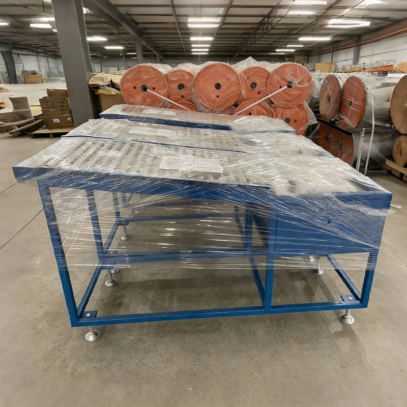
The winding and storage rack provides temporary cable storage between the haul-off and the final take-up. It allows the take-up section to operate smoothly and helps separate short fluctuations in upstream and downstream speed.
The tension control rack regulates cable tension before winding. Stable tension prevents loose coils, overlapping turns, uneven reel filling, and deformation of soft insulation. Tension control is particularly important when the line uses automatic coiling or when the finished cable is wound onto large reels.
Dual-Axis Take-Up Machine
The dual-axis take-up machine winds finished cable onto reels. Two-axis operation can support continuous or semi-continuous production, depending on the selected configuration. When one reel is full, the machine can prepare the second reel for a faster changeover and reduced downtime.
Take-up equipment can be customized for different reel sizes, cable diameters, winding patterns, and production speeds. Accurate traverse control distributes the cable evenly across the reel and reduces the risk of collapsed or unstable packages.
Wire And Cable Extrusion Line
Extrusion Technology for Different Polymer Materials
A major strength of a professional cable extrusion line is its ability to process different polymer materials using suitable screw and barrel configurations. Each material has a particular melting behavior, viscosity range, thermal sensitivity, and cooling requirement. A universal operating recipe is rarely suitable for every compound.
PVC Insulation and Sheathing
PVC is widely used for building wires, flexible cables, control cables, and general-purpose electrical products. It offers a balance of cost, flexibility, flame performance, and processability. However, PVC can be sensitive to excessive heat and residence time. Improper temperature control may result in discoloration, degradation, surface roughness, or unstable melt pressure.
A PVC line typically requires carefully balanced barrel temperatures, stable feeding, appropriate screw compression, and effective cooling. The temperature controller supplied with the extrusion system uses a logical tracer-type controller manufactured by RKC in Japan, with an SSR electrical circuit and a stated temperature deviation of approximately plus or minus 2 degrees Celsius. Stable temperature control helps maintain uniform melt viscosity and reduces variation in cable dimensions.
Polyethylene and LDPE
Polyethylene compounds are used for insulation, sheathing, communication cables, and other applications that require good electrical insulation and moisture resistance. LDPE generally flows at lower viscosity than many engineering polymers, so screw design and die selection must prevent excessive melt sagging or dimensional instability.
Cooling conditions are also important. The cable must be sufficiently supported while the polymer solidifies. Inadequate cooling can cause deformation, while excessive or uneven cooling may create internal stress and dimensional variation.
LSZH Materials
Low Smoke Zero Halogen compounds are used where reduced smoke and halogen-free performance are required, including public buildings, transportation facilities, data centers, and infrastructure projects. LSZH compounds often contain high levels of mineral fillers and may require higher torque, specialized screws, controlled feeding, and careful temperature management.
Because LSZH compounds can be sensitive to excessive shear and poor dispersion, the screw should provide effective melting and mixing without generating unnecessary heat. Stable pressure and controlled residence time help reduce surface defects, unmelted particles, and inconsistent insulation thickness.
Teflon and High-Temperature Materials
Teflon and other high-temperature insulation materials require specialized processing conditions. The extrusion system must be designed for the material’s high processing temperature and particular flow characteristics. Barrel construction, heater capacity, temperature sensors, crosshead design, and cooling arrangements must all be selected accordingly.
High-temperature materials also require careful safety procedures and suitable ventilation. A production line intended for these compounds should not be treated as interchangeable with a standard PVC line without evaluating the complete thermal and mechanical requirements.
Nylon and Engineering Plastics
Nylon insulation is used in applications requiring abrasion resistance, mechanical strength, and a durable surface. Nylon is sensitive to moisture, so proper material drying and storage are important before extrusion. Moisture can produce bubbles, surface defects, and unstable processing.
The line design should provide appropriate drying, feeding, melt temperature, die configuration, and cooling control. These features help produce a smooth, consistent layer around the conductor.
Screw and Barrel Design
The screw is the central working component of an extrusion machine. It conveys solid material from the feed zone, compresses and melts the polymer, mixes the melt, and meters it toward the crosshead. Screw geometry affects output, melt temperature, pressure stability, dispersion, and surface quality.
The listed equipment uses screw designs with L/D ratios of 25:1 or 26:1, depending on the model. This range is widely used for cable insulation and sheathing because it provides sufficient residence time for melting and homogenization without requiring an excessively long machine.
A higher L/D ratio can improve thermal uniformity and mixing, but it may also increase residence time and shear heat. The correct design depends on the compound and target output. A screw optimized for PVC may not provide the same result when used with LSZH, PE, or Teflon.
Important screw design variables include:
- Screw diameter, which influences output range and maximum product size.
- L/D ratio, which affects melting time and mixing capability.
- Compression ratio, which influences compaction and melt pressure.
- Flight depth, which affects conveying and metering capacity.
- Barrier sections, which separate solid and molten material during melting.
- Mixing sections, which improve dispersion of additives and fillers.
- Flight pitch, which affects conveying speed and shear input.
Yessjet configures screw geometry according to the material family, production target, and customer application rather than relying solely on a standard configuration. Engineering evaluation can consider polymer viscosity, desired line speed, processing temperature, conductor size, and finished insulation thickness. This approach helps reduce process variation that might otherwise be incorrectly attributed to the die, conductor tension, or cooling system.
Temperature Control and Melt Stability
Temperature management is one of the most important factors in cable extrusion. The goal is not simply to reach a target temperature. The complete thermal profile must allow the polymer to feed, melt, mix, meter, and exit through the die at a stable viscosity.
The barrel is divided into independently controlled zones. Depending on the machine configuration, the line may use multiple heating zones together with separate die and crosshead zones. Each zone can be adjusted to create a suitable temperature gradient for the selected material.
| Material | Feed Zone | Compression Zone | Metering Zone | Die Zone |
|---|---|---|---|---|
| HDPE | 160–175°C | 190–200°C | 210–220°C | 215–225°C |
| Flexible PVC | 150–160°C | 165–175°C | 170–180°C | 175–185°C |
| XLPE | 100–115°C | 120–130°C | 125–135°C | 130–140°C |
| LSZH | 155–165°C | 170–180°C | 175–185°C | 180–190°C |
The temperatures in this table are starting references rather than universal production recipes. Actual settings depend on the compound formulation, screw design, output rate, tooling, ambient conditions, and required surface finish. Operators should confirm the actual melt temperature and pressure instead of relying only on controller setpoints.
Stable temperature control reduces several common defects, including rough surfaces, bubbles, melt fracture, gels, discoloration, poor bonding, and inconsistent diameter. The RKC temperature controller and SSR control circuit used in the line are selected to support accurate regulation and responsive heating control.
Production Models and Capacity Range
The equipment range includes extruders with screw diameters from 40 mm to 120 mm. The model selection determines the available output, finished diameter range, drive motor power, and suitability for different cable sizes.
| Model | Screw Diameter | L/D Ratio | Maximum RPM | PVC Output | LDPE Output | LSZH Output | Finished Diameter | Drive Motor |
|---|---|---|---|---|---|---|---|---|
| EX-40G | 40 mm | 26:1 | 120 | 24 kg/h | 14 kg/h | — | 0.8–3 mm | 11 kW |
| EX-40S | 40 mm | 26:1 | 120 | 48 kg/h | 14 kg/h | — | 0.8–3 mm | 15 kW |
| EX-50G | 50 mm | 26:1 | 120 | 60 kg/h | 35 kg/h | — | 1–6 mm | 15 kW |
| EX-50S | 50 mm | 26:1 | 120 | 75 kg/h | 35 kg/h | — | 1–6 mm | 18.5 kW |
| EX-60G | 60 mm | 26:1 | 120 | 100 kg/h | 60 kg/h | 22 kg/h | 2–8 mm | 22 kW |
| EX-60S | 60 mm | 26:1 | 120 | 120 kg/h | 60 kg/h | 24 kg/h | 2–8 mm | 30 kW |
| EX-70G | 70 mm | 26:1 | 120 | 140 kg/h | 95 kg/h | 36 kg/h | 3–15 mm | 30 kW |
| EX-70S | 70 mm | 26:1 | 120 | 160 kg/h | 95 kg/h | 40 kg/h | 3–15 mm | 37 kW |
| EX-80G | 80 mm | 26:1 | 110 | 200 kg/h | 130 kg/h | 48 kg/h | 5–20 mm | 37 kW |
| EX-80S | 80 mm | 26:1 | 110 | 250 kg/h | 130 kg/h | 52 kg/h | 5–20 mm | 45 kW |
| EX-90G | 90 mm | 26:1 | 110 | 280 kg/h | 180 kg/h | 65 kg/h | 8–25 mm | 45 kW |
| EX-90S | 90 mm | 26:1 | 110 | 320 kg/h | 180 kg/h | 70 kg/h | 8–25 mm | 55 kW |
| EX-100G | 100 mm | 25:1 | 100 | 380 kg/h | 240 kg/h | 90 kg/h | 10–30 mm | 55 kW |
| EX-100S | 100 mm | 25:1 | 100 | 450 kg/h | 240 kg/h | 100 kg/h | 10–30 mm | 75 kW |
| EX-120G | 120 mm | 25:1 | 100 | 500 kg/h | — | — | 15–40 mm | 90 kW |
| EX-120S | 120 mm | 25:1 | 100 | 600 kg/h | — | — | 15–40 mm | 110 kW |
The values shown are maximum reference capacities. Actual output depends on compound density, screw design, melt temperature, tooling, conductor size, cooling conditions, line speed, and product specification. Selecting the correct model requires balancing capacity against product range. An oversized extruder may operate inefficiently at very low output, while an undersized extruder may limit future production expansion.
Closed-Loop Diameter Control
Modern extrusion lines increasingly use closed-loop diameter control to improve dimensional consistency. A non-contact gauge measures the product after cooling and sends feedback to the PLC or drive system. The controller can then adjust haul-off speed or screw speed to correct deviations from the target diameter.
When correctly configured, the system can maintain tight outer diameter tolerances during steady production. It also reduces reliance on manual sampling and allows operators to identify process drift before a large amount of material is produced outside specification.
Closed-loop control must be configured carefully because the gauge is physically separated from the die. The distance between the die and measuring point creates a transport delay. At higher speeds, a change at the die may take several seconds to reach the gauge. If the control system responds too aggressively, it may overcorrect and create oscillation. Proper deadband, response time, filtering, and proportional settings are therefore necessary.
It is also important to understand what an outer diameter gauge cannot detect. A cable may have a correct average outside diameter while its insulation is eccentric. This can happen if the conductor is off-center or if the die shifts during operation. For critical cable products, the production line should combine accurate tooling alignment, stable tension, conductor guiding, and suitable wall thickness inspection.
Haul-Off Tension and Conductor Protection
Haul-off tension influences both insulation dimensions and conductor quality. The caterpillar must pull the product consistently, but excessive clamping force can mark the insulation or elongate the conductor. This is especially important for fine stranded conductors and products below approximately 0.5 square millimeters.
Excessive conductor tension can permanently increase conductor length and alter the lay relationship in stranded constructions. This may influence resistance per kilometer, flexibility, and dimensional stability. A mismatch between pay-off braking, haul-off speed, and take-up tension is a common cause of this problem.
The correct caterpillar configuration depends on the cable diameter and compound hardness. Soft materials such as flexible TPU or silicone require lower belt pressure and wider contact surfaces. Harder cable jackets may tolerate higher pressure, but the pressure must still be sufficient only to prevent slippage.
The best results are obtained when the control system receives feedback from dancer rolls or tension sensors at both the pay-off and take-up. This allows the line to maintain a stable tension window during acceleration, steady production, reel filling, and deceleration.
Manufacturing Strengths and Engineering Approach
The performance of an extrusion line depends not only on component selection but also on the engineering process used to build, assemble, test, and commission the equipment. Shanghai Yessjet Precise Machinery Co., Ltd. combines product customization with complete line integration. This enables the company to evaluate the entire production process rather than supplying an isolated extruder.
Application-Based Configuration
Before selecting a model, engineers can review the customer’s conductor construction, insulation or sheath compound, finished diameter, target output, line speed, reel size, and required production standards. This information determines screw diameter, screw geometry, crosshead configuration, cooling length, haul-off capacity, measurement system, and take-up design.
Such application-based configuration is an advantage over choosing equipment only by motor power or nominal output. A line that appears powerful on paper may still produce poor cable if the screw, crosshead, cooling section, and tension system are not matched to the product.
Mechanical Alignment and Assembly
Every section of a continuous cable line must be aligned along the conductor path. Misalignment can lead to eccentric insulation, unstable entry into the crosshead, excessive die wear, or irregular contact with the haul-off belts. Assembly and commissioning therefore require attention to the centerline of the pay-off, straightener, extruder, cooling tank, printing section, haul-off, and take-up.
Mechanical inspection should include frame stability, shaft runout, gearbox condition, reel positioning, guide alignment, belt tracking, and take-up traverse accuracy. These checks create a reliable foundation for later electrical and process adjustments.
Electrical Integration
The PLC-based control system connects the individual units into one operating sequence. Interlocks can prevent the line from starting if cooling water, air pressure, guarding, or emergency circuits are not ready. Alarms can identify high temperature, motor overload, loss of feedback, diameter deviation, or tension problems.
Yessjet also designs control architectures with future automation in mind. Spare input and output capacity, pre-wired terminals, and documented signal maps can simplify later integration of automatic coilers, cutters, strapping stations, and robotic palletizing equipment. This forward-compatible design avoids the need to replace the entire control system when production volumes increase.
Factory Testing and Commissioning
Before shipment, a complete line should be checked for mechanical operation, electrical wiring, temperature response, motor rotation, safety circuits, sensor signals, PLC sequences, and communication between machine sections. Factory testing helps identify issues before installation at the customer’s site.
After installation, commissioning normally includes centerline alignment, material trial runs, temperature optimization, screw speed testing, haul-off calibration, diameter gauge setup, printing adjustment, take-up tension tuning, and operator training. These steps help transfer the equipment from a collection of machines into a stable production system.
Advantages Over Conventional and Disconnected Equipment
Compared with conventional lines that rely heavily on manual intervention, the integrated system offers several practical advantages.
More Consistent Product Quality
PLC coordination, stable temperature control, diameter measurement, and tension management reduce process variation. Operators can monitor actual operating conditions rather than relying only on visual inspection or periodic sampling.
Higher Production Efficiency
Accurate synchronization allows the extruder to operate closer to its intended capacity. Automated take-up, storage, and coiling reduce interruptions and help maintain continuous output. Faster changeovers also improve equipment utilization.
Lower Material Waste
Startup waste is unavoidable in many extrusion processes, but it can be reduced through stored recipes, controlled acceleration, stable heating, and diameter feedback. Early alarms also prevent long lengths of cable from being produced during a fault condition.
Better Adaptability
The equipment can be configured for multiple material families and product sizes. Interchangeable tooling and material-specific screw designs allow manufacturers to serve different markets without investing in a separate complete factory line for every product type.
Easier Expansion
A control system prepared for future automation allows customers to add coiling, cutting, packaging, or robotic palletizing at a later stage. This supports phased investment and reduces the risk of creating a production bottleneck at the end of the line.
Automatic Coiling and Robotic Palletizing Integration
End-of-line automation is becoming increasingly important as extrusion speeds increase. Manual coiling and palletizing can limit output even when the extruder, cooling system, and haul-off have sufficient capacity. Automatic coilers, reel changers, strapping systems, and robotic stackers help manufacturers maintain a continuous flow of finished product.
Successful integration requires more than placing a coiling machine beside the extrusion line. The control system must provide accurate meter counting, a dependable cut signal, speed coordination, coil transfer logic, and confirmation that the new package is ready. Without these signals, cable slack may accumulate or the cutter may operate at the wrong moment.
The extrusion line should therefore be designed with end-of-line communication from the beginning. The PLC can exchange signals with the coiler, packaging system, or robot through dedicated inputs and outputs or a suitable industrial communication system. This approach improves safety and makes future expansion easier.
For small-gauge building wire produced at high speed, automatic coiling can be especially valuable. The product may leave the cooling system faster than an operator can form and package coils manually. Automated equipment maintains consistent coil diameter, package weight, and labeling while reducing repetitive labor.
Robotic palletizing can further improve material handling. A robot can place coils or reels according to a programmed pattern, maintain pallet stability, and prepare completed pallets for storage or shipment. Safety fencing, light curtains, emergency stops, and package detection should be included in the complete automation design.
Retrofitting Existing Cable Lines
Many cable manufacturers operate extrusion equipment that remains mechanically sound but uses outdated relay logic, analog controllers, or obsolete drives. In such cases, a complete replacement may not always be necessary. A targeted retrofit can improve performance while preserving usable mechanical equipment.
High-value retrofit upgrades often include:
- Replacement of obsolete PLCs with modern programmable control platforms.
- Installation of a touchscreen HMI with product recipe management.
- Replacement of analog temperature controllers with digital PID controllers.
- Integration of laser diameter measurement.
- Addition of closed-loop haul-off and tension control.
- Replacement of outdated inverters and motor drives.
- Preparation for MES, production data collection, or remote diagnostics.
Not every machine is suitable for retrofit. Before upgrading the controls, engineers should inspect the extruder barrel, screw, gearbox, crosshead, frame, cooling tanks, shafts, and feed system. A control upgrade cannot compensate for severe mechanical wear or structural misalignment.
A structured assessment can include screw and barrel wear measurement, gearbox backlash testing, thermal imaging of heater performance, electrical cabinet inspection, sensor verification, and spare-parts availability review. This process prevents customers from investing in a new control system on a mechanical platform that requires replacement soon afterward.
Yessjet’s retrofit evaluation approach is intended to identify which components can be retained, which should be refurbished, and which require replacement. This can provide a practical path to improved productivity when a complete new line is not economically appropriate.
Quality Control During Cable Production
Quality control should be integrated into the production process rather than performed only after the cable has been completed. The extrusion line can support several levels of inspection, from operator checks to automated measurement and final laboratory testing.
Incoming Material Control
Polymer compounds should be checked for identification, moisture, contamination, and storage condition. Nylon and other moisture-sensitive materials may require drying before feeding. Conductors should be inspected for diameter, surface damage, oxidation, strand condition, and cleanliness.
Process Monitoring
Important process parameters include barrel temperature, die temperature, melt pressure, screw speed, haul-off speed, line speed, cooling water temperature, product diameter, and take-up tension. Monitoring these parameters helps operators distinguish between material problems, mechanical problems, and control problems.
Dimensional Inspection
Finished diameter should be measured continuously where possible. Manual sampling can still be used to verify the gauge and to measure insulation thickness at multiple positions around the cable. Eccentricity should be checked because average diameter alone cannot confirm uniform wall thickness.
Electrical Testing
Depending on the product, testing may include spark testing, conductor resistance, insulation resistance, high-voltage testing, elongation, tensile strength, aging performance, and flame behavior. A stable extrusion process reduces the likelihood of pinholes, thin spots, contamination, and internal defects that could cause electrical failure.
Surface and Marking Inspection
The cable surface should be checked for roughness, bubbles, drag marks, color variation, die lines, and contamination. Printed information should be legible, correctly positioned, and resistant to rubbing under the intended application conditions.
Maintenance Recommendations
Preventive maintenance protects output quality and extends equipment life. The extrusion screw and barrel should be inspected periodically for wear, especially when processing abrasive or mineral-filled compounds. Excessive clearance can reduce output stability and increase energy consumption.
Temperature sensors, heaters, SSR circuits, fans, cooling pumps, and water lines should be checked regularly. A failed sensor may cause an incorrect temperature reading, while a blocked cooling circuit may affect cable diameter and surface quality.
Pay-off brakes, dancer rolls, guides, caterpillar belts, bearings, gearboxes, and take-up shafts require routine inspection. Belt wear or incorrect pressure can mark the insulation. A damaged guide may scratch the conductor or create unstable positioning before the crosshead.
Laser gauges and other measurement instruments should be kept clean and calibrated according to the manufacturer’s recommendations. The operator should compare gauge readings with verified manual measurements during scheduled maintenance.
Electrical cabinets should be cleaned and inspected for loose terminals, overheating, dust accumulation, damaged cables, and cooling fan failure. PLC programs, recipes, and parameter settings should be backed up so that production data can be restored after a component replacement.
Energy Efficiency and Operational Economy
Energy consumption in a cable extrusion line comes primarily from barrel heating, drive motors, cooling systems, compressed air, and auxiliary equipment. Improving process stability can reduce energy use because less material is scrapped and fewer production runs need to be repeated.
Correct screw selection is important. A screw that is too small for the required output may operate at excessive speed, while an oversized screw may consume energy inefficiently at low throughput. Proper barrel insulation, accurate heating control, and efficient cooling water circulation can also reduce operating costs.
Variable-frequency drives and coordinated motor control allow the line to match energy use to actual production requirements. During standby or changeover, the equipment can operate at reduced speed rather than full capacity. A modern control system can also record operating data to identify periods of excessive energy consumption or repeated process instability.
Applications
The wire and cable extrusion line can be configured for a broad range of products, including building wires, flexible cords, control cables, appliance wires, automotive wires, communication cables, industrial cables, and protective sheaths.
Small-diameter products typically require precise conductor guiding, fast response from the diameter control system, accurate take-up, and careful tension regulation. Larger cables require higher output capacity, stronger haul-off equipment, longer cooling sections, and larger reels.
The system is suitable for manufacturers that need to produce several cable families on one platform. By changing tooling, adjusting recipes, and using material-appropriate process settings, the same production facility can serve different customers and applications while maintaining process control.
How to Select the Correct Model
Choosing the correct extrusion line begins with the product rather than the machine. Buyers should define the conductor material and size, insulation or sheath material, finished diameter, wall thickness, maximum output, target line speed, reel dimensions, printing requirements, and future expansion plans.
The following questions help determine the correct configuration:
- What conductor diameter and construction will be processed?
- Will the line run PVC, PE, LSZH, Teflon, nylon, or several materials?
- What is the minimum and maximum finished cable diameter?
- What output in kilograms per hour is required?
- What line speed is needed for the target product?
- Is continuous diameter measurement required?
- Will the product be wound onto reels, formed into coils, or both?
- Is automatic cutting or packaging planned?
- What electrical and safety standards apply to the finished cable?
- Will the line need to connect with factory data systems in the future?
After these requirements are established, the screw diameter, model, motor power, crosshead, cooling length, haul-off, gauge, printing unit, and take-up can be selected. Yessjet can provide customized line configurations rather than limiting customers to a single standard arrangement.
Frequently Asked Questions
What is a wire and cable extrusion line used for?
It is used to apply a controlled layer of insulation or protective sheathing around a conductor. The line also cools, measures, marks, hauls, stores, tensions, and winds the finished wire or cable.
Which materials can the equipment process?
Depending on the screw, barrel, crosshead, and temperature configuration, the equipment can process PVC, LDPE, LSZH, Teflon, nylon, and other suitable thermoplastic compounds. Material-specific testing is recommended before production approval.
Why are different screw designs needed?
Different polymers have different melting temperatures, viscosities, shear sensitivities, and mixing requirements. A screw designed for PVC may not provide the best results with LSZH or high-temperature materials. Matching the screw to the material improves melt stability and product consistency.
Can the line control cable diameter automatically?
Yes. A laser diameter gauge can measure the product continuously and send feedback to the PLC or drive system. The controller can adjust line speed or extrusion output within configured limits.
Does an outer diameter gauge measure insulation eccentricity?
No. An outer diameter gauge measures the outside dimension but does not directly determine whether the insulation wall is uniform around the conductor. Eccentricity also depends on conductor centering, die alignment, tooling condition, and tension stability.
What is the purpose of the cooling tanks?
Cooling tanks remove heat from the extruded polymer and stabilize the finished diameter. Pre-cooling and main cooling sections allow the material to solidify gradually and reduce deformation or sticking.
How does haul-off speed affect cable quality?
Haul-off speed affects draw-down and wall thickness. If the haul-off runs too fast, the insulation may become too thin. If it runs too slowly, the cable may become oversized. Stable synchronization with extruder output is essential.
Can the system produce both small and large cables?
The available models cover different screw diameters, output ranges, and finished diameter ranges. The correct model depends on the intended product family. A line designed for a narrow product range may require different tooling or auxiliary equipment to process larger cables.
Can automatic coiling be added later?
Yes, if the control system and mechanical layout are prepared for expansion. Accurate meter counting, cutting signals, coil transfer logic, spare I/O, and documented communication signals make later installation easier.
Is retrofitting possible for an older cable line?
Retrofitting may be possible when the barrel, screw, gearbox, frame, crosshead, and other mechanical components remain within acceptable condition. A technical assessment should be completed before deciding whether to upgrade controls or replace the entire line.
What information should be provided when requesting a quotation?
Customers should provide conductor details, material type, finished diameter, wall thickness, production speed, target output, reel size, printing requirements, electrical standards, factory power conditions, and desired automation level. These details allow the supplier to prepare a more accurate configuration.
Conclusion
A modern wire and cable extrusion line is a complete production system rather than a single extruder. Its performance depends on the coordination of material feeding, screw and barrel design, temperature control, crosshead tooling, cooling, diameter measurement, haul-off tension, printing, storage, take-up, and packaging.
The equipment supplied by Shanghai Yessjet Precise Machinery Co., Ltd. combines high-capacity extrusion components, imported barrel and screw technology, PLC-based control, RKC temperature regulation, customized process engineering, and integration with automatic coiling and robotic palletizing systems. The range of models supports different output levels and finished cable sizes, while application-specific configurations help manufacturers process materials such as PVC, PE, LSZH, Teflon, and nylon.
Compared with disconnected or manually controlled equipment, an integrated line provides more stable production, improved dimensional consistency, lower waste, easier data management, and better opportunities for future automation. Through factory testing, customized engineering, retrofit assessment, and commissioning support, the company helps cable manufacturers build practical production systems suited to their present requirements and future growth.
For manufacturers seeking reliable cable production equipment, the most important selection criteria are not only nominal output and motor power. The complete process must be evaluated, including material compatibility, screw geometry, temperature stability, tension control, measurement, cooling, take-up, safety, maintenance, and expansion capability. A correctly engineered line provides the foundation for efficient, repeatable, and commercially competitive wire and cable production.
References
1. IEC 60227, Polyvinyl Chloride Insulated Cables of Rated Voltages Up to and Including 450/750 V.
2. UL 83, Thermoplastic-Insulated Wires and Cables.
3. ISO 9001, Quality Management Systems — Requirements.
4. Plastics Extrusion Technology, principles of screw design, polymer melting, metering, and die processing.
5. Cable Manufacturing Technology, guidance on conductor preparation, insulation extrusion, cooling, testing, and take-up.
6. Industrial Automation and PLC Control Engineering, principles of closed-loop control, sensor integration, interlocks, and production data management.
7. Manufacturer technical data for EX-series wire and cable extrusion equipment.
8. Technical guidance on polymer temperature profiling, haul-off tension control, cooling system design, and cable dimensional inspection.