LANGUAGE
 中文简体
中文简体 русский
 Français
 Español
 Português
 عربى
عربى
Content
- 1 Overview of the Wire and Cable Extrusion Line
- 2 Key Advantages Over Conventional Cable Extrusion Equipment
- 3 Extrusion Machine Design and Manufacturing Strengths
- 4 Detailed Production Process
- 5 Technical Specifications and Model Selection
- 6 Advanced Process Control for Consistent Quality
- 7 Retrofitting Existing Cable Extrusion Lines
- 8 End-of-Line Automation and Expansion Potential
- 9 Maintenance and Operating Recommendations
- 10 Applications
- 11 Why Choose a Complete Customized Solution
- 12 Frequently Asked Questions
- 12.1 What materials can the extrusion line process?
- 12.2 How do I select the correct extruder model?
- 12.3 What is the difference between the G and S models?
- 12.4 Can the line produce both small wires and larger cables?
- 12.5 How is insulation thickness controlled?
- 12.6 Does an outer diameter gauge measure wall thickness?
- 12.7 What causes uneven insulation thickness?
- 12.8 Can an older extrusion line be upgraded?
- 12.9 What should be considered before adding an automatic coiler?
- 12.10 How can the equipment improve production efficiency?
- 12.11 What information is needed for a customized quotation?
- 13 Conclusion
- 14 References
- 15 Product: Wire And Cable Extrusion Line
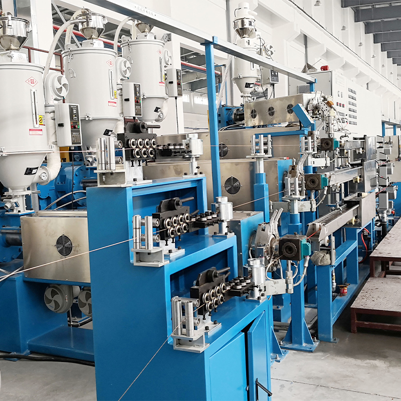
Wire and cable manufacturing demands more than a high-output extruder. A reliable production system must coordinate conductor pay-off, polymer melting, crosshead extrusion, diameter measurement, cooling, printing, haul-off, tension control, winding, and finished-cable take-up. When these processes operate as one synchronized system, manufacturers can produce insulated wires and sheathed cables with consistent dimensions, stable electrical performance, clean surfaces, and dependable production efficiency.
The Wire and Cable Extrusion Line is designed as an integrated manufacturing solution for companies producing PVC, PE, LSZH, Teflon, nylon, and other insulated or jacketed wire and cable products. Its modular configuration allows the line to be adapted to different conductor sizes, polymer types, finished diameters, production speeds, and packaging requirements. From the first pay-off stand to the final cable reel, each unit contributes to continuous and controlled production.
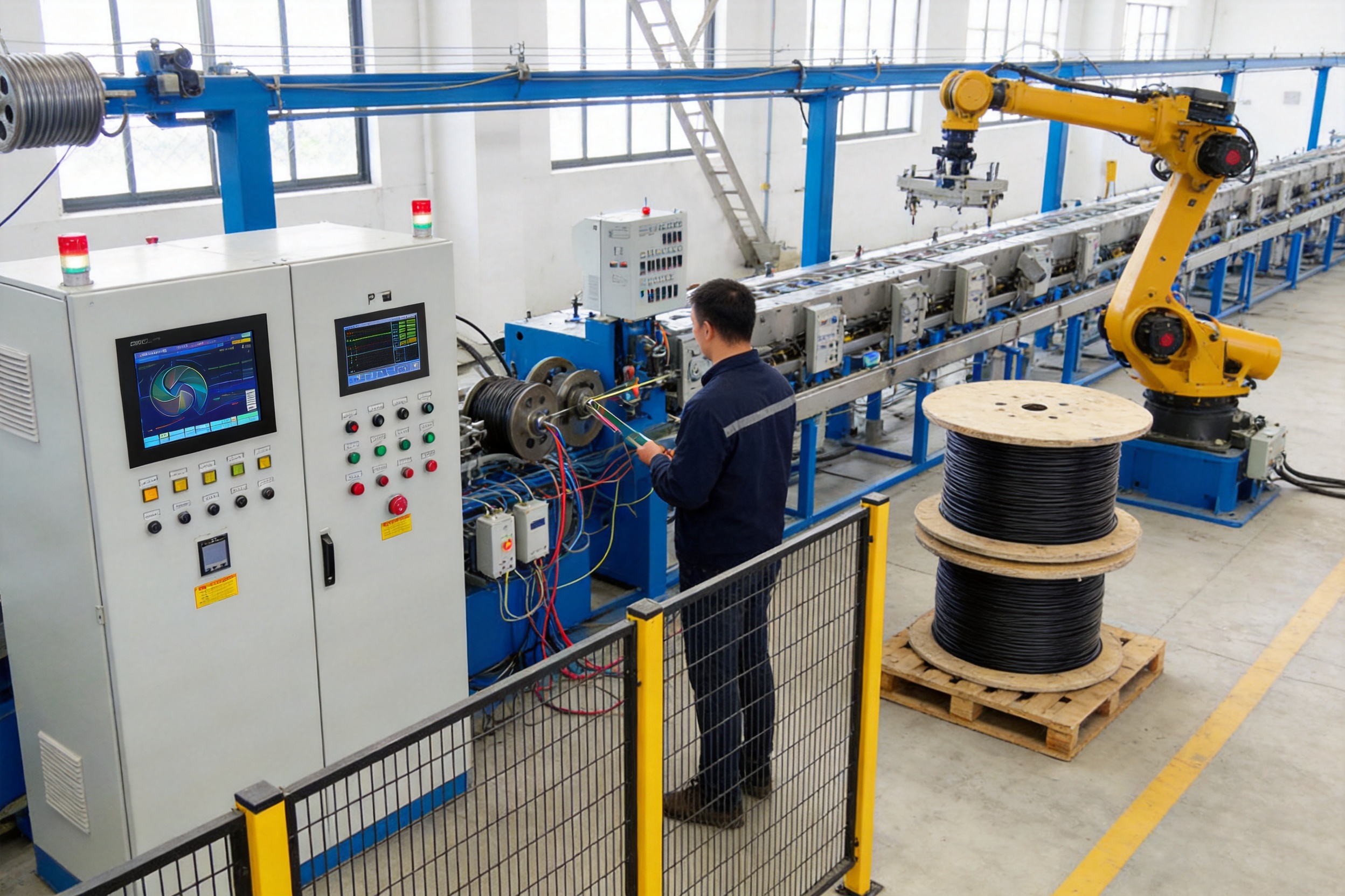
Compared with basic extrusion equipment, an integrated line offers better process coordination, fewer manual handling steps, improved material utilization, and more consistent product quality. The system is also suitable for future automation upgrades, including automatic coiling, robotic palletizing, production data collection, and closed-loop diameter control.
Overview of the Wire and Cable Extrusion Line
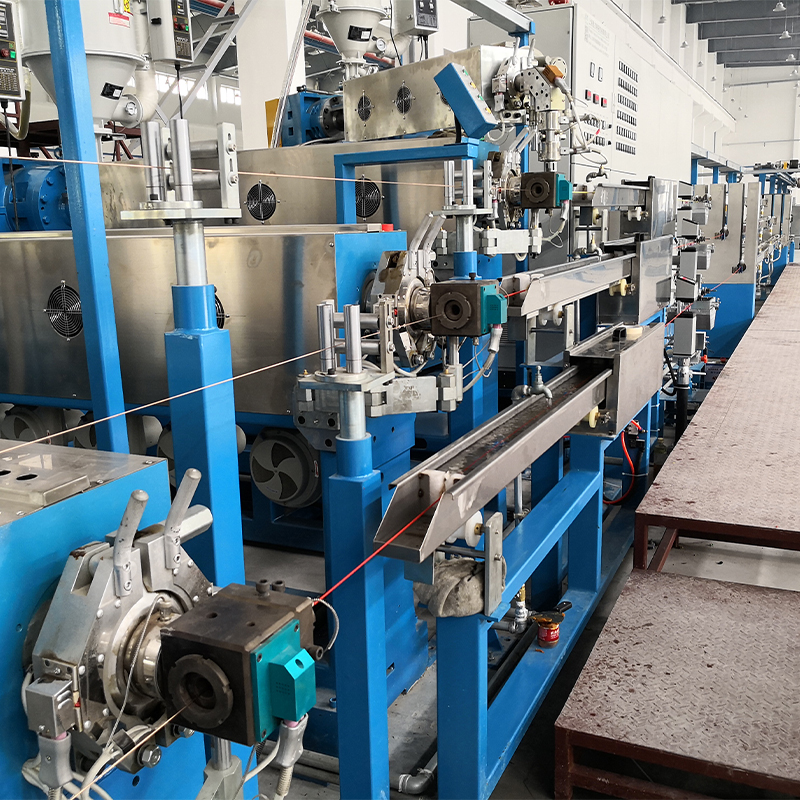
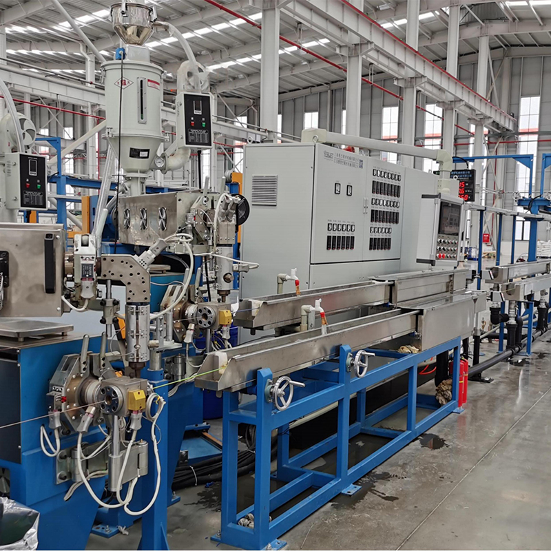
A wire and cable extrusion line applies a continuous layer of insulation or protective sheathing around a conductor. The conductor may be a solid copper wire, stranded copper conductor, aluminum conductor, or another compatible conductive core. Plastic pellets or compound are fed into the extruder, heated, mixed, and pushed through a crosshead die. The polymer forms a uniform coating around the moving conductor before passing through cooling, measurement, printing, haul-off, and winding equipment.
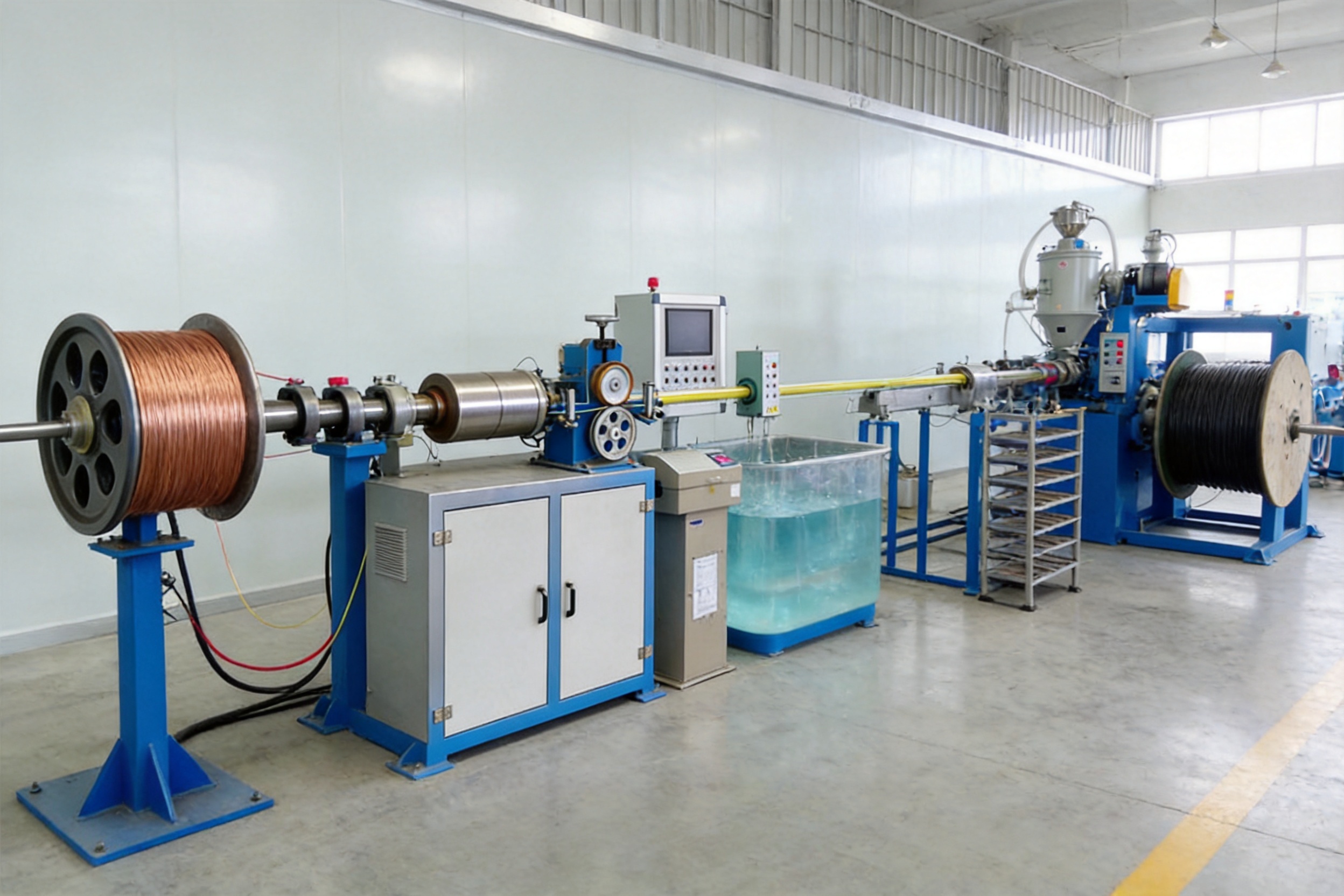
The complete production line normally includes the following sections:
- Motorized or controlled pay-off stand
- Wire straightening and alignment unit
- Single-screw extrusion machine
- Crosshead and die assembly
- Main electrical control and operation cabinet
- Outer diameter measuring instrument
- Pre-cooling water tank
- Ink printing machine
- Main cooling water tank
- Dual-wheel or caterpillar haul-off unit
- Winding and storage rack
- Tension control rack
- Dual-axis take-up machine
Each section is arranged to maintain a stable production path. The conductor enters the line under controlled tension, passes through the extrusion crosshead, and receives a precise polymer layer. After cooling and inspection, the finished cable is marked and transferred to the take-up system. This continuous arrangement reduces handling damage and supports long production runs.
The line can also be configured for different cable structures. A smaller extrusion machine may be used for building wire and small insulated conductors, while larger models are suitable for medium-sized cables and thicker protective jackets. The selection of screw diameter, drive motor, cooling length, haul-off capacity, and take-up reel size depends on the required output and finished cable dimensions.
Key Advantages Over Conventional Cable Extrusion Equipment
Integrated Process Coordination
A major advantage of a complete extrusion line is the coordination of all production stages through a central control system. Pay-off speed, extruder output, haul-off speed, cooling conditions, printing, meter counting, and take-up tension must remain synchronized. If one section operates too quickly or too slowly, the conductor may become over-tensioned, the insulation may vary in thickness, or the cable may accumulate slack.
The integrated control architecture helps operators manage the line from a centralized operation box. Programmable logic controller technology allows the system to coordinate start-up, normal operation, emergency stopping, speed changes, alarm conditions, and production sequences. This is more efficient than operating separate machines with disconnected controls.
High Extrusion Capacity
The extruder is equipped with a screw and barrel configuration designed for continuous polymer processing. The available models cover screw diameters from 40 mm to 120 mm, allowing users to select a suitable machine for different production requirements. Depending on the model and material, the maximum extrusion capacity ranges from approximately 24 kg per hour to 600 kg per hour.
This broad capacity range gives manufacturers a practical way to match equipment investment with actual production demand. A compact model can support low- to medium-volume production without unnecessary energy consumption, while a larger model can supply high-output cable lines for industrial production.
Material-Specific Screw and Barrel Selection
Different polymers require different processing conditions. PVC, LDPE, LSZH, Teflon, nylon, and other compounds differ in melting behavior, viscosity, thermal sensitivity, shear requirements, and cooling characteristics. A screw design that performs well with one material may not deliver the same quality with another.
The line supports material-specific screw and barrel selection. This makes it possible to configure the plasticizing system according to the compound family and intended output. A suitable screw geometry can improve melting stability, reduce unmelted particles, support more uniform mixing, and help maintain consistent insulation thickness.
For heat-sensitive materials, process control is especially important. Excessive shear or excessive residence time may increase melt temperature and cause degradation. For materials that require more mixing or higher output, a different compression ratio and metering configuration may be more appropriate. Selecting the correct screw is therefore a production decision rather than a simple replacement-parts choice.
Stable Temperature Control
The extrusion line uses logical tracer-type temperature controllers and SSR electrical circuits to maintain stable barrel temperatures. The stated temperature deviation can be controlled within approximately ±2°C under suitable operating conditions. Stable temperature control supports uniform melting and reduces fluctuations in melt viscosity.
Consistent temperature is directly related to product quality. If the polymer is too cold, incomplete melting and surface defects may occur. If it is too hot, the material may degrade, discolor, generate gas, or lose its required mechanical properties. Stable zone control helps the operator establish a repeatable processing window for each cable material.
Reduced Dependence on Manual Operation
Manual control creates variation between operators and increases the risk of production errors. A complete line automates many repetitive tasks, including synchronized speed adjustment, temperature monitoring, cooling management, meter counting, and take-up operation.
Automation does not eliminate the need for skilled operators. Instead, it allows operators to focus on process supervision, quality verification, material preparation, and preventive maintenance. This improves labor productivity and makes production procedures easier to standardize across shifts.
Flexible Product Range
The extrusion line is suitable for a wide range of finished diameters. Depending on the selected model, the stated finished diameter range extends from approximately 0.8 mm to 40 mm. This enables the same equipment platform to support small insulated wires, medium cables, and larger jacketed products when the correct crosshead and tooling are installed.
Product flexibility is valuable for cable manufacturers that serve multiple markets. A line can be configured for building wires, appliance wires, control cables, communication-related conductors, automotive wires, industrial cables, and other products, subject to the correct material, die, conductor, and process requirements.
Wire And Cable Extrusion Line
Extrusion Machine Design and Manufacturing Strengths
Precision Screw and Barrel Manufacturing
The screw and barrel form the core of the extrusion machine. Their internal geometry determines how efficiently polymer pellets are conveyed, compressed, melted, mixed, and metered. Manufacturing accuracy is therefore essential for stable pressure and output.
Advanced manufacturing begins with careful material selection and dimensional control. The screw flight geometry, compression section, metering section, and tip configuration must correspond to the intended polymer and operating range. The barrel must maintain accurate internal alignment and suitable wear resistance so that the clearance between screw and barrel remains within an acceptable range during service.
During production, machining quality influences several operating characteristics. A properly manufactured screw can help maintain steady melt pressure, while poor geometry may cause output pulsation, excessive shear heating, or inadequate mixing. Consistent surface finishing also contributes to smooth material flow and easier cleaning during material changes.
Modular Engineering for Different Materials
One of the strengths of a professional cable extrusion manufacturer is the ability to configure equipment instead of supplying a one-size-fits-all machine. Material selection, conductor type, target diameter, output rate, line speed, and required surface finish should all be evaluated before finalizing the machine.
For PVC insulation, the extrusion system must support controlled heating and stable residence time because PVC can be sensitive to excessive temperature and shear. For polyethylene materials, the machine must provide effective melting and stable metering at the required output. LSZH compounds may require careful temperature management and screw design because their processing window can differ from conventional PVC or PE.
Special materials such as Teflon and nylon may require dedicated barrel, screw, crosshead, and temperature configurations. The line design should also consider drying requirements, material feeding behavior, die construction, and cooling conditions. A manufacturer with experience in different compound families can reduce the risk of selecting unsuitable components.
Electrical Control and Automation Integration
The electrical control system is responsible for converting mechanical equipment into a coordinated production line. It monitors temperature, speed, tension, water conditions, alarms, and emergency circuits. A programmable controller provides an organized method for managing these functions.
A modern control cabinet may include a PLC, touch-screen human-machine interface, motor drives, temperature controllers, solid-state relays, circuit protection, contactors, safety relays, and communication terminals. The exact configuration depends on the production requirements and customer preferences.
The control system can be designed with additional input and output capacity for future expansion. This is an important advantage when a customer initially purchases the extrusion line but plans to add automatic coiling, robotic stacking, laser diameter measurement, or manufacturing execution system integration later.
Forward-compatible control design reduces the cost and complexity of future upgrades. Spare terminals, documented signal maps, and planned communication interfaces can make it easier to connect downstream equipment without replacing the entire control architecture.
Quality Control During Assembly
Manufacturing quality depends not only on component design but also on assembly accuracy. The extruder, crosshead, haul-off, cooling tanks, storage rack, and take-up unit must be aligned along a common production centerline. Misalignment can introduce conductor stress, uneven coating, or cable surface marking.
Assembly procedures should include mechanical alignment, rotation checks, drive testing, electrical continuity checks, temperature-control verification, emergency-stop testing, and dry-run operation. Water tanks should be checked for leakage, drainage performance, guide positioning, and accessibility for cleaning.
Before shipment, a complete production line can be reviewed as a system rather than as a collection of separate machines. This approach helps identify communication errors, incorrect motor rotation, sensor faults, loose wiring, insufficient guarding, or unsuitable cable routing before installation at the customer’s facility.
Detailed Production Process
1. Pay-Off and Conductor Preparation
The pay-off stand releases the conductor at a controlled speed. Stable pay-off is essential because variations in conductor tension can affect insulation thickness and cable geometry. A conductor that is released too tightly may stretch or pull the coating off-center. A conductor that is released too loosely may form loops, vibrate, or enter the crosshead without stable alignment.
Motorized pay-off equipment is useful for continuous production because it can coordinate conductor release with line speed. Depending on the conductor size and reel format, the pay-off may include reel supports, braking, guide rollers, dancer control, and automatic or assisted reel loading.
Before extrusion, the conductor should be checked for cleanliness, surface condition, diameter, strand integrity, and compatibility with the selected product specification. Copper oxidation, contamination, or damaged strands can affect adhesion and electrical performance.
2. Straightening and Alignment
The straightening stand removes unwanted curvature from the conductor and guides it toward the extrusion crosshead. Proper alignment helps position the conductor at the center of the die.
Centering is particularly important for thin insulation layers. A small deviation at the crosshead can create eccentric wall thickness, even when the outer diameter appears correct. The straightening unit should therefore be adjusted carefully and inspected regularly for worn rollers, excessive pressure, or incorrect guide positions.
3. Plasticizing and Extrusion
Plastic material enters the hopper and moves into the heated barrel. The rotating screw conveys the material through feed, compression, and metering zones. Mechanical shear and controlled heat transform the pellets or compound into a homogeneous melt.
The melt then travels through the adapter and crosshead. Inside the crosshead, the conductor passes through the center while the polymer flows around it. The die determines the initial geometry of the insulation or sheath.
Stable extrusion requires a balance among screw speed, material feed rate, melt temperature, melt pressure, conductor speed, and die dimensions. Increasing line speed without adjusting polymer output may reduce wall thickness. Increasing screw speed without confirming cooling capacity may create excessive melt temperature or insufficient solidification.
4. Diameter Measurement
The outer diameter measuring instrument provides information about the size of the extruded cable. Continuous measurement allows the operator to identify variations that may result from unstable output, conductor movement, temperature changes, die wear, or haul-off speed fluctuations.
A diameter gauge can also be integrated into a closed-loop control system. Depending on the system design, feedback may adjust screw speed, haul-off speed, or another process variable. This can improve steady-state diameter consistency and reduce operator intervention.
However, outer diameter measurement does not directly confirm wall thickness eccentricity. A cable may have a correct average outer diameter while the insulation is thinner on one side and thicker on the other. For demanding applications, the production line may be supplemented with eccentricity or wall-thickness measurement equipment.
5. Pre-Cooling and Main Cooling
Freshly extruded polymer leaves the crosshead at an elevated temperature. The pre-cooling tank provides initial cooling and helps stabilize the surface before the cable enters the main cooling section.
The main water tank removes additional heat and solidifies the insulation or jacket. Cooling length, water temperature, water circulation, cable immersion, and guide arrangement all influence the final product condition.
Insufficient cooling may cause surface deformation, sticking, or dimensional instability during take-up. Excessive or uneven cooling may create internal stress, especially in some semi-crystalline materials. The cooling system should therefore be designed according to polymer type, cable diameter, line speed, and required mechanical performance.
6. Ink Printing and Product Identification
The ink printing machine marks the wire or cable with information such as product model, voltage rating, manufacturer identification, meter markings, date codes, or other customer requirements.
Clear and durable printing supports product traceability and simplifies installation. Printing quality depends on cable surface condition, ink selection, print-head positioning, line speed, drying conditions, and maintenance of the ink system.
7. Haul-Off and Tension Control
The haul-off unit pulls the cooled cable through the line at a controlled speed. A dual-wheel or caterpillar design provides stable traction while reducing the risk of slippage. The contact pressure must be adjusted according to cable diameter, surface hardness, and jacket material.
Too little pressure may cause slipping and speed variation. Too much pressure may mark the surface or compress the cable. Soft materials require particular care because excessive clamping force can leave visible impressions.
Haul-off speed has a direct effect on insulation thickness. At a fixed extrusion output, increasing the haul-off speed generally reduces the amount of polymer deposited per unit length. The relationship between output and line speed must be controlled carefully to achieve the target wall thickness.
Tension control should include the pay-off, haul-off, storage rack, and take-up sections. Dancer rollers or other tension feedback devices can help compensate for changing reel diameter and acceleration or deceleration conditions.
8. Storage Rack and Take-Up
The winding and storage rack provides temporary cable storage and helps separate the haul-off process from the take-up process. This is useful when the take-up reel changes or when the line must continue operating for a short period during downstream handling.
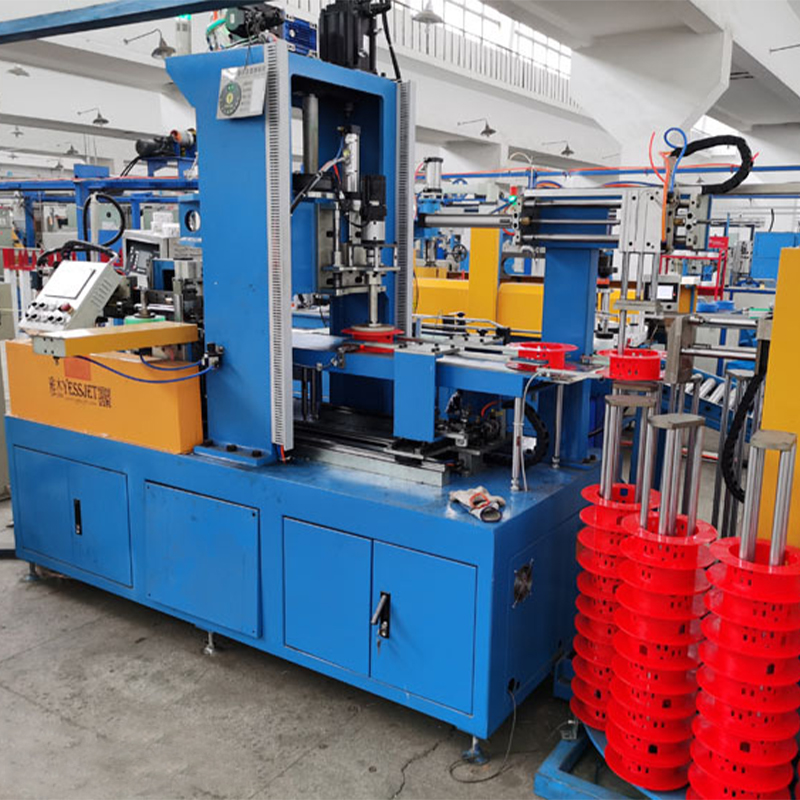
The dual-axis take-up machine winds the finished cable onto reels. Automatic or semi-automatic reel changes can reduce production interruptions and improve operator safety. Proper traverse control distributes the cable evenly across the reel and avoids loose layers, crossing, or edge buildup.
Take-up tension must remain stable as the reel diameter increases. If tension is too high, the cable may stretch or become tightly compressed. If tension is too low, the winding may become loose and unstable during transport.
Technical Specifications and Model Selection
The following table summarizes the principal extrusion models and the available output ranges stated for the product series. Actual production capacity depends on material type, formulation, screw configuration, conductor size, operating temperature, die design, and line speed.
| Model | Screw Diameter | L/D Ratio | Maximum RPM | PVC Capacity kg/h | LDPE Capacity kg/h | LSZH Capacity kg/h | Finished Diameter mm | Drive Motor kW |
|---|---|---|---|---|---|---|---|---|
| EX-40G | 40 mm | 26:1 | 120 | 24 | 14 | — | 0.8–3 | 11 |
| EX-40S | 40 mm | 26:1 | 120 | 48 | 14 | — | 0.8–3 | 15 |
| EX-50G | 50 mm | 26:1 | 120 | 60 | 35 | — | 1–6 | 15 |
| EX-50S | 50 mm | 26:1 | 120 | 75 | 35 | — | 1–6 | 18.5 |
| EX-60G | 60 mm | 26:1 | 120 | 100 | 60 | 22 | 2–8 | 22 |
| EX-60S | 60 mm | 26:1 | 120 | 120 | 60 | 24 | 2–8 | 30 |
| EX-70G | 70 mm | 26:1 | 120 | 140 | 95 | 36 | 3–15 | 30 |
| EX-70S | 70 mm | 26:1 | 120 | 160 | 95 | 40 | 3–15 | 37 |
| EX-80G | 80 mm | 26:1 | 110 | 200 | 130 | 48 | 5–20 | 37 |
| EX-80S | 80 mm | 26:1 | 110 | 250 | 130 | 52 | 5–20 | 45 |
| EX-90G | 90 mm | 110 | 110 | 280 | 180 | 65 | 8–25 | 45 |
| EX-90S | 90 mm | 110 | 110 | 320 | 180 | 70 | 8–25 | 55 |
| EX-100G | 100 mm | 25:1 | 100 | 380 | 240 | 90 | 10–30 | 55 |
| EX-100S | 100 mm | 25:1 | 100 | 450 | 240 | 100 | 10–30 | 75 |
| EX-120G | 120 mm | 25:1 | 100 | 500 | — | — | 15–40 | 90 |
| EX-120S | 120 mm | 25:1 | 100 | 600 | — | — | 15–40 | 110 |
The G and S versions in the series provide different output and drive configurations within similar screw diameter classes. The correct choice should be based on the required material throughput, expected operating schedule, finished cable range, and future production plans. It is generally preferable to select a machine that can meet the target output without operating continuously at its absolute limit.
Manufacturers should also consider the difference between maximum rated capacity and practical production capacity. Maximum values are normally influenced by material type, melt temperature, die pressure, cooling ability, and product geometry. A stable production rate with consistent quality is often more valuable than a higher output that creates frequent dimensional variation or process interruptions.
Advanced Process Control for Consistent Quality
Screw Design and Melt Homogeneity
Screw geometry influences the quality of the polymer melt before it reaches the crosshead. Important parameters include screw diameter, length-to-diameter ratio, compression ratio, flight pitch, feed-section design, barrier configuration, and mixing elements.
The listed models generally use L/D ratios of 25:1 or 26:1. This range provides sufficient residence time for many wire and cable insulation materials while maintaining a practical machine length. A longer screw can support improved melting and mixing, but it may also increase shear heat and residence time. The best configuration depends on the compound and output target.
Barrier screw designs may improve the separation of solid and molten phases during processing. Mixing sections can help distribute additives, pigments, flame-retardant components, and other formulation ingredients. However, mixing elements must be selected carefully because excessive shear can damage heat-sensitive materials.
Temperature Profiling
Temperature settings should be treated as a process recipe rather than a fixed number. The feed zone, compression zone, metering zone, adapter, and die can each require different temperatures.
For HDPE, a gradually rising temperature profile may support smooth melting and help prevent premature melting near the feed throat. Flexible PVC may require a more controlled and relatively flat profile to limit degradation. LSZH compounds often require careful balancing of melting performance and thermal stability.
| Material | Feed Zone | Compression Zone | Metering Zone | Die Zone |
|---|---|---|---|---|
| HDPE | 160–175°C | 190–200°C | 210–220°C | 215–225°C |
| Flexible PVC | 150–160°C | 165–175°C | 170–180°C | 175–185°C |
| XLPE | 100–115°C | 120–130°C | 125–135°C | 130–140°C |
| LSZH | 155–165°C | 170–180°C | 175–185°C | 180–190°C |
These values are starting references only. Actual settings must be validated against the specific compound supplier’s recommendations, melt pressure, surface appearance, insulation dimensions, electrical test results, and production speed.
Closed-Loop Diameter Regulation
A laser diameter gauge can measure the outer diameter continuously and provide feedback to the control system. When properly tuned, closed-loop control can compensate for moderate process fluctuations and maintain tight dimensional stability.
The distance between the die and the gauge creates a transport delay. The cable must travel from the extrusion point through the cooling tank before the measurement becomes available. If the control system reacts too aggressively, it may overcorrect because the measured result reflects a process condition that occurred several seconds earlier.
Effective control therefore requires suitable deadband settings, response parameters, and production recipes. Operators should also distinguish between a genuine process disturbance and normal measurement variation. Stable melt pressure, reliable encoder feedback, clean gauge lenses, and correct sensor alignment are essential for effective closed-loop operation.
Electrical and Mechanical Testing
Dimensional inspection should be combined with electrical and mechanical testing. Typical checks may include conductor resistance, insulation resistance, high-voltage or spark testing, tensile strength, elongation, adhesion, surface appearance, print durability, and finished-reel inspection.
Testing requirements depend on product type and applicable customer or industry standards. Production data should be linked to material batch, machine recipe, operator, reel number, and inspection results whenever possible. This improves traceability and simplifies corrective action if a nonconformity is detected.
Retrofitting Existing Cable Extrusion Lines
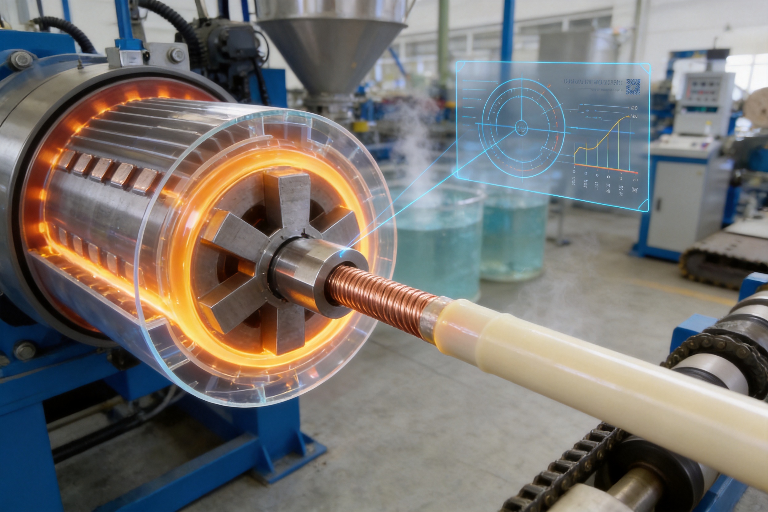
Many manufacturers operate extrusion lines that remain mechanically useful but have outdated control systems. Relay-based logic, analog temperature controllers, aging drives, and unavailable electrical components can make maintenance difficult and prevent integration with modern production software.
A complete replacement is not always necessary. A structured retrofit assessment can determine whether the existing barrel, screw, gearbox, frame, crosshead, cooling system, and take-up equipment remain suitable for continued service.
High-Value Retrofit Improvements
- Replacement of obsolete PLC systems
- Installation of a modern touch-screen HMI
- Recipe management and production parameter storage
- Digital PID temperature controllers with automatic tuning
- Laser diameter measurement
- Servo-driven haul-off with tension feedback
- Modern variable-frequency drives
- Expanded alarm, data logging, and safety functions
- Communication interfaces for future MES integration
Mechanical replacement should be based on measured condition rather than age alone. A gearbox that operates smoothly and maintains acceptable backlash may not need replacement. Similarly, a cooling trough that is structurally sound and corrosion-free may continue to perform effectively after a control upgrade.
Mechanical Conditions That May Limit Retrofitting
Some problems cannot be solved by replacing the PLC or temperature controllers. Severe frame distortion can prevent accurate alignment. Excessive screw and barrel wear can cause unstable output and poor mixing. Damaged crosshead threads can prevent reliable centering. A worn hopper may create inconsistent material feeding or compound segregation.
A proper evaluation should include screw and barrel wear measurement, gearbox inspection, frame alignment checks, heater and thermocouple testing, drive-condition assessment, crosshead inspection, and cooling-system verification. This prevents investment in electronic upgrades when the mechanical platform is already approaching the end of its useful life.
End-of-Line Automation and Expansion Potential
Production efficiency is not determined by the extruder alone. At high line speeds, manual coiling, reel handling, and palletizing can become the main bottlenecks. Integrating automatic coiling machines, strapping equipment, labeling stations, and robotic stackers can increase throughput and reduce repetitive manual handling.
Automatic coiling requires reliable communication between the extrusion line and the coiler. Important signals include meter counting, line speed, cable-present status, cut commands, reel-ready status, coil-transfer confirmation, and emergency-stop coordination.
The cable must be transferred from one coil to the next without creating excessive slack. The cutter must operate at the correct moment, and the new core must be ready before the finished cable reaches the transfer point. If these sequences are not planned in the original control architecture, a later retrofit may require extensive PLC and wiring modifications.
A forward-compatible line can reserve input and output capacity, provide documented signal definitions, and include communication terminals for future downstream equipment. This gives manufacturers the option to add automation as production volume increases rather than paying for every system at the beginning.
Robotic palletizing can further reduce manual handling after coiling or reel winding. A robot can identify finished units, pick them using a suitable gripper, and place them according to a programmed pallet pattern. The final design must consider coil weight, reel dimensions, product protection, pallet stability, and workplace safety.
Maintenance and Operating Recommendations
Daily Checks
Operators should inspect material feeding, barrel temperature, melt pressure, cooling-water condition, cable alignment, printing quality, haul-off traction, reel winding, and emergency-stop operation at the beginning of each shift.
Water tanks should be kept clean so that particles do not scratch the cable surface or block circulation. Printing components should be cleaned according to ink-system requirements. The diameter gauge should be checked for contamination and correct alignment.
Periodic Maintenance
Periodic maintenance should include inspection of heaters, thermocouples, drive belts, bearings, gearboxes, guide rollers, dancer mechanisms, haul-off belts, reel supports, and electrical connections. Loose terminals may cause intermittent faults or localized heating.
The screw and barrel should be cleaned when changing to incompatible materials or when deposits affect output stability. Cleaning procedures must be appropriate for the material and machine construction. Improper cleaning tools or excessive mechanical force may damage internal surfaces.
Process Documentation
Manufacturers should maintain records of material batch, screw speed, line speed, temperature profile, melt pressure, cooling conditions, conductor size, die dimensions, finished diameter, and inspection results. Recipe documentation makes it easier to reproduce successful production conditions and diagnose defects.
Preventive maintenance records should include dates, replaced components, measured wear, calibration results, and outstanding issues. This creates a history of equipment condition and supports decisions about future upgrades.
Applications
The Wire and Cable Extrusion Line can support the production of many types of insulated and sheathed products, including:
- Building and construction wires
- Flexible appliance wires
- Control cables
- Industrial insulated conductors
- Automotive and equipment wires
- Low-voltage power cables
- Communication-related cable products
- Flame-retardant and low-smoke cable products
- Specialty polymer-insulated wires
Application suitability depends on the selected extruder, crosshead, tooling, compound, conductor structure, cooling arrangement, and applicable product standard. A technical review should be completed before production of a new cable type.
Why Choose a Complete Customized Solution
A complete customized solution provides advantages beyond the purchase of an individual extruder. The supplier can evaluate the entire production path, including conductor handling, extrusion, cooling, measurement, printing, haul-off, take-up, and future packaging automation.
This approach helps prevent mismatched equipment. For example, an extruder may have sufficient output, but the cooling tank may be too short for the selected material and line speed. A take-up machine may support the reel size but lack the tension range needed for a thin cable. A printing machine may operate correctly at low speed but fail to maintain legibility at the required production rate.
System-level engineering addresses these relationships before equipment manufacture. It also simplifies installation, commissioning, operator training, spare-parts planning, and after-sales support.
The manufacturing strengths behind the line include material-specific equipment configuration, screw and barrel selection, PLC-based automation, temperature-control integration, mechanical alignment, modular expansion, and production-line testing. These capabilities allow the equipment to be adapted to different customer requirements rather than forcing every user into the same configuration.
Frequently Asked Questions
What materials can the extrusion line process?
The line can be configured for materials including PVC, PE, LDPE, LSZH, Teflon, nylon, and other suitable wire and cable compounds. The correct screw, barrel, temperature profile, crosshead, die, and cooling arrangement depend on the selected material.
How do I select the correct extruder model?
Selection should consider conductor diameter, finished cable diameter, insulation or sheath thickness, material type, target output, production speed, operating schedule, and future expansion. The largest available model is not automatically the best choice. A properly sized machine usually provides better efficiency and process stability.
What is the difference between the G and S models?
The G and S versions provide different output and drive configurations within the same general screw-diameter class. The S models generally offer higher listed capacity and motor power in the larger model groups. Final selection should be based on the required material throughput and product range.
Can the line produce both small wires and larger cables?
The product series covers different finished-diameter ranges. Smaller models are suitable for smaller wire products, while larger models support thicker insulation and cable jackets. Producing a broad range may require interchangeable crossheads, dies, guides, and take-up arrangements.
How is insulation thickness controlled?
Insulation thickness is influenced by extruder output, conductor speed, haul-off speed, die geometry, melt temperature, conductor centering, and cooling conditions. A diameter gauge can monitor outer diameter, while additional eccentricity or wall-thickness equipment may be used for more detailed control.
Does an outer diameter gauge measure wall thickness?
No. An outer diameter gauge measures the external size of the cable. It cannot directly confirm whether the insulation is evenly distributed around the conductor. Wall-thickness or eccentricity measurement is required to evaluate the thinnest and thickest sections.
What causes uneven insulation thickness?
Common causes include conductor misalignment, incorrect die centering, unstable tension, worn tooling, melt-pressure fluctuation, inconsistent material feeding, unsuitable temperature settings, and irregular haul-off speed. A systematic inspection of the complete line is usually required.
Can an older extrusion line be upgraded?
Many older lines can be upgraded if the frame, extruder, screw, barrel, gearbox, crosshead, and mechanical alignment remain serviceable. Common upgrades include PLC replacement, digital temperature control, modern drives, HMI installation, laser measurement, and tension-feedback systems.
What should be considered before adding an automatic coiler?
The line should provide reliable meter counting, cut signals, cable-speed information, coiler-ready feedback, transfer sequencing, and emergency-stop communication. Mechanical space, coil dimensions, production speed, cable flexibility, and operator access must also be evaluated.
How can the equipment improve production efficiency?
Efficiency improves through coordinated line control, reduced manual handling, stable extrusion output, automated temperature management, continuous measurement, controlled cooling, synchronized haul-off, and optimized take-up. Future coiling and robotic palletizing can further reduce end-of-line bottlenecks.
What information is needed for a customized quotation?
Important information includes conductor material and diameter, insulation or sheath material, finished cable diameter, wall thickness, target line speed, required output, reel dimensions, factory power supply, available floor space, printing requirements, and desired automation level.
Conclusion
The Wire and Cable Extrusion Line is a complete production platform for manufacturers seeking reliable insulation and sheathing performance across a broad range of cable products. Its key advantages include material-specific screw and barrel configurations, multiple capacity classes, PLC-based coordination, stable temperature control, controlled pay-off and take-up, continuous diameter monitoring, integrated cooling, printing, and tension management.
The equipment is designed not only for current production requirements but also for future development. Modular engineering allows manufacturers to add advanced measurement, automatic coiling, robotic stacking, data collection, and other automation functions as market demand increases.
Strong manufacturing results depend on the complete relationship between machine design, component quality, assembly accuracy, process control, and technical support. By evaluating the entire line rather than a single extruder, manufacturers can achieve more consistent cable dimensions, improved material utilization, fewer production interruptions, and better long-term operating value.
For companies planning a new cable production facility, replacing aging equipment, or upgrading an existing line, a customized extrusion solution provides a practical path toward higher productivity and more dependable quality.
References
1. General principles of thermoplastic polymer extrusion and screw design for continuous processing.
2. Industrial practices for wire and cable insulation, jacketing, cooling, haul-off, and take-up control.
3. Technical guidance for programmable logic controller integration in continuous manufacturing lines.
4. Engineering principles for melt temperature management, polymer residence time, and extrusion pressure stability.
5. Quality-control practices for cable diameter, eccentricity, insulation resistance, conductor resistance, and spark testing.
6. Manufacturer-provided product specifications for the EX-40G through EX-120S extrusion machine series.