LANGUAGE
 中文简体
中文简体 русский
 Français
 Español
 Português
 عربى
عربى
Content
- 1 What Is a Motorized Take-Up Equipment Machine?
- 2 Core Functions in Cable Production
- 3 Why Motorized Take-Up Equipment Is Better Than Basic Winding Systems
- 4 Advanced Tension Control for High-Quality Cable Winding
- 5 Traverse Pitch and Layer Stability
- 6 Spool Change Automation and Scrap Reduction
- 7 Mechanical Compatibility and Spool Interface Design
- 8 Control Architecture for Extrusion Line Integration
- 9 Manufacturing Strengths and Engineering Capabilities
- 10 Safety Features for Industrial Operation
- 11 Applications Across Wire and Cable Industries
- 12 Operating Procedure and Maintenance Recommendations
- 13 How to Select the Correct Machine Configuration
- 14 Economic Benefits and Return on Investment
- 15 Quality Assurance and Production Consistency
- 16 Why Choose a Specialized Manufacturer
- 17 Q&A: Motorized Take-Up Equipment Machine
- 17.1 What materials can the machine wind?
- 17.2 Why is tension control important?
- 17.3 What is taper tension?
- 17.4 Should a dancer or load cell be used?
- 17.5 Can the machine be added to an existing extrusion line?
- 17.6 Can the machine use different spool sizes?
- 17.7 How does automatic spool changing reduce scrap?
- 17.8 How is traverse pitch selected?
- 17.9 What should be checked if the cable has periodic tension variation?
- 17.10 Is the machine suitable for high-speed production?
- 17.11 What information should be provided for a quotation?
- 18 Conclusion
- 19 References
- 20 Product: Motorized Take-Up Equipment Machine
In modern wire and cable manufacturing, the take-up process is much more than the final step of winding finished product onto a spool. It is a precision operation that directly affects cable appearance, dimensional stability, insulation performance, production continuity, labor efficiency, and the total cost of each kilometer produced. A well-designed motorized take-up equipment machine must coordinate winding torque, spool rotation, traverse movement, cable tension, line speed, spool capacity, and changeover operations in real time.
Shanghai Yessjet Precise Machinery Co., Ltd. develops and manufactures motorized take-up equipment machines for wire and cable extrusion lines, cable production systems, and specialized winding applications. Its equipment is designed to receive finished wire or cable from an upstream production line and wind it evenly onto a spool while maintaining controlled tension throughout the entire winding cycle.
Compared with basic mechanical winders or manually operated take-up devices, a modern motorized take-up machine provides more accurate tension control, more consistent layer formation, faster spool handling, improved operator safety, and better compatibility with automated production lines. It can be configured for building wire, power cable, communication cable, automotive cable, flexible cable, armored cable, coaxial cable, and other continuous products.
The machine can use torque motors, frequency-converted motors, servo drives, reducers, dancer systems, load cells, traverse mechanisms, automatic stop functions, and safety protection systems. These components work together to ensure that the cable is wound smoothly from the empty core to the full spool without excessive stretching, loose layers, crossed turns, insulation damage, or unnecessary material waste.
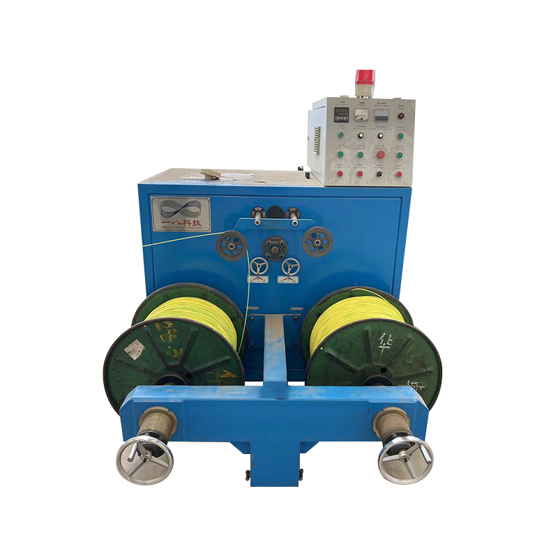
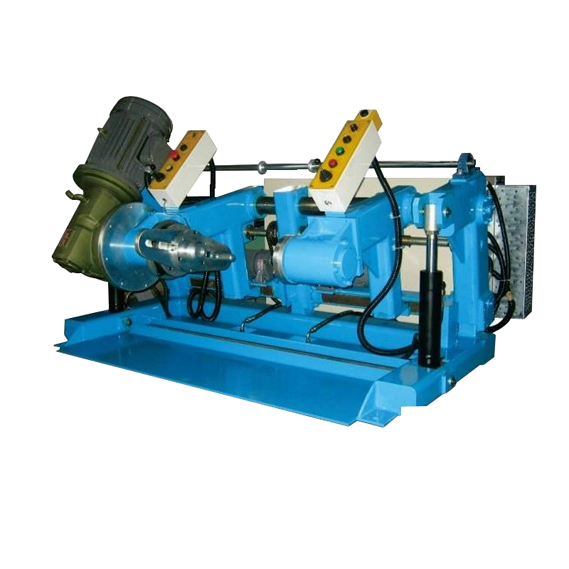
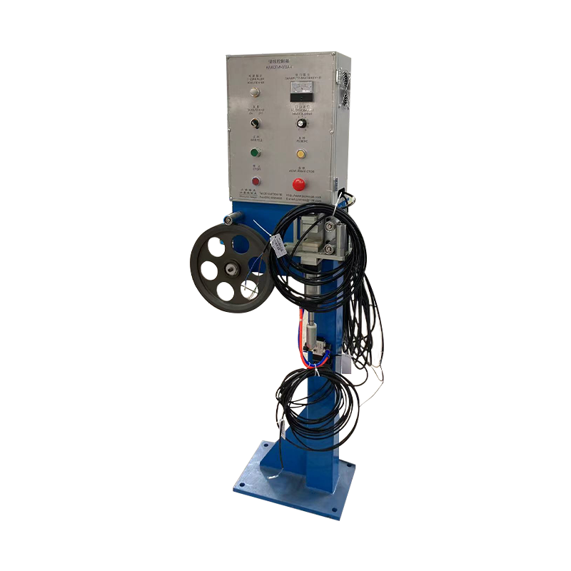
Motorized Take-Up Equipment Machine
What Is a Motorized Take-Up Equipment Machine?
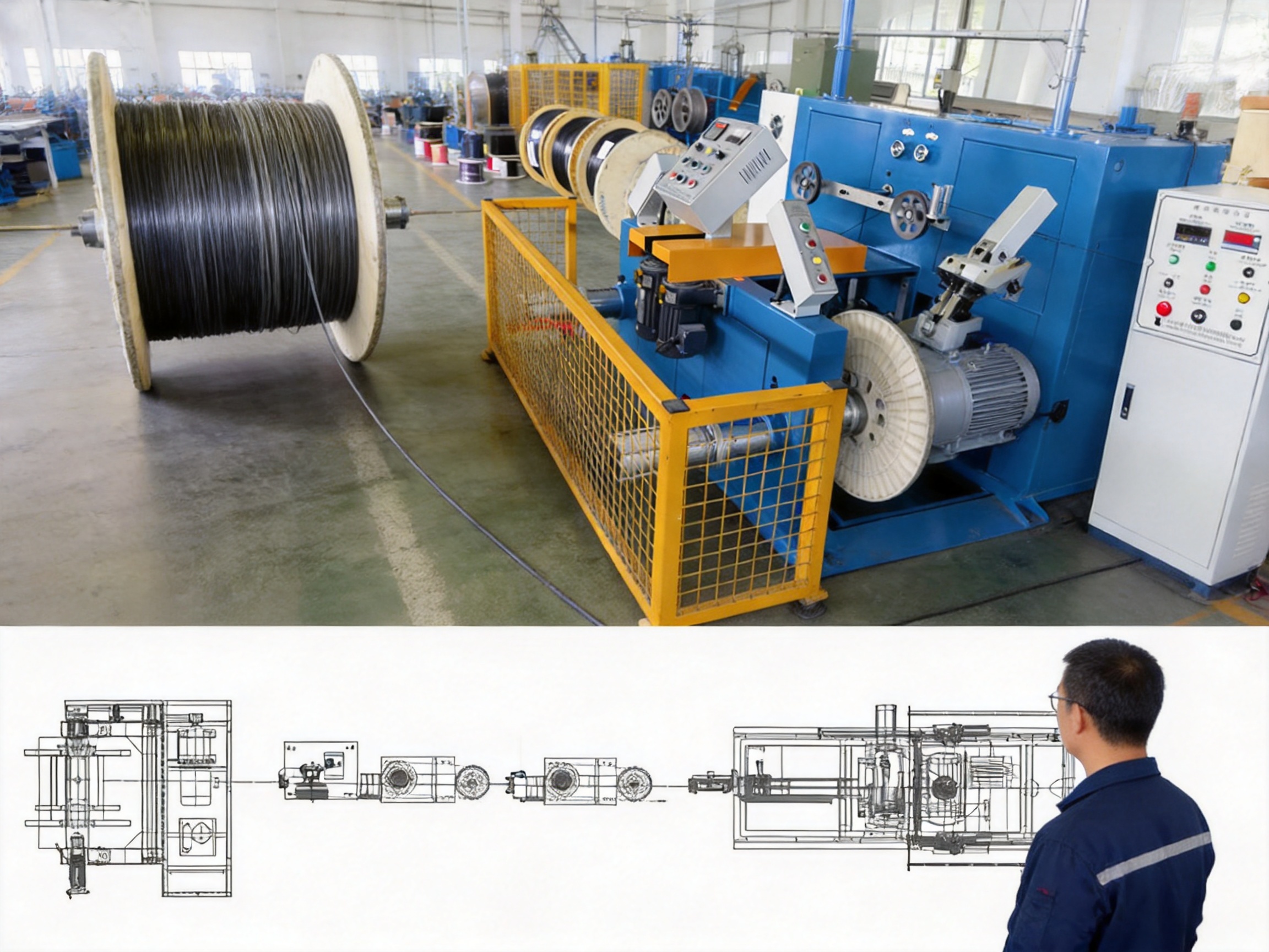
A motorized take-up equipment machine is an electrically driven device used to collect, wind, store, and organize continuously produced wire, cable, filament, or similar flexible materials. It is normally installed at the downstream end of an extrusion line or cable processing line. As the upstream equipment produces cable, the take-up machine rotates a spool and guides the cable across the spool width in a controlled traverse pattern.
The term “take-up” describes the action of collecting the finished product. In a wire and cable line, the take-up machine must synchronize with the haul-off, cooling system, measuring equipment, spark tester, diameter gauge, marking system, and other upstream equipment. If the take-up speed is too low, the cable may accumulate, sag, or become tangled. If it is too high, the cable can be stretched, deformed, or subjected to excessive tension.
A motorized design provides controlled driving force rather than relying only on passive spool rotation. The motor can adjust torque and speed according to the changing winding diameter. At the beginning of the winding process, the cable is placed close to the spool core, where the effective winding radius is small. As additional layers are formed, the diameter increases and the required rotational speed decreases for the same linear cable speed. A suitable control system compensates for this changing geometry automatically.
The machine generally includes a winding shaft or spool support, drive motor, reducer or transmission system, traverse mechanism, tension control system, control cabinet, meter counter interface, operating panel, emergency stop circuit, and protective guards. Depending on the application, it may also include a turret arrangement, flying cutter, automatic spool exchange system, tail securing mechanism, accumulator interface, or robotic handling function.
Core Functions in Cable Production
The primary function of the equipment is to wind cable onto a spool in a compact and orderly arrangement. However, reliable take-up performance depends on several closely related functions.
Controlled Winding Tension
The machine applies a controlled winding force so the cable remains properly seated on the spool without being compressed excessively. Stable tension is essential for maintaining cable geometry and protecting insulation, jackets, shielding layers, and conductor positioning.
Variable-Speed Spool Rotation
Because the winding diameter increases continuously, spool rotation must change during the production cycle. A frequency-converted motor or servo drive can modify rotational speed according to the line speed and current spool diameter. This allows the cable’s linear speed to remain synchronized with the extrusion line.
Traverse Distribution
The traverse system moves the cable laterally across the spool. It controls the pitch between adjacent turns and reverses direction near the flange. Accurate traverse movement prevents gaps, overlaps, unstable edge beads, and crossed layers.
Length and Full-Spool Detection
A meter counter or production control signal can determine when the programmed cable length has been reached. The machine may then stop automatically, begin a spool change sequence, or send a signal to the line control system.
Process Coordination
The take-up machine can exchange signals with the extrusion line, haul-off, accumulator, cutting system, and centralized production control system. Proper coordination prevents line interruptions and allows the equipment to respond to speed changes, emergency stops, cable breaks, and spool replacement requirements.
Operator and Equipment Protection
Safety guards, emergency stop buttons, interlocks, protective covers, overload protection, and controlled acceleration reduce risks during operation. These features are particularly important because large cable spools can carry substantial mass and rotating components can store significant mechanical energy.
Why Motorized Take-Up Equipment Is Better Than Basic Winding Systems
Basic winding systems may be suitable for simple, low-speed, low-tension applications, but they often become inadequate as cable diameter, production speed, spool size, or product value increases. A motorized take-up machine provides a more comprehensive solution.
First, it can respond continuously to changing winding conditions. A passive or mechanically limited system may not compensate effectively for the increase in spool diameter. This can produce unstable tension, loose winding at the outer layers, or excessive force at the core. Motorized control allows the winding torque and rotational speed to be adjusted throughout the complete spool build.
Second, an automated traverse mechanism creates a more uniform winding pattern. Manual guiding depends heavily on operator skill and attention. Even experienced operators may struggle to maintain consistent pitch at high production speeds. Automatic traverse control provides repeatable layer formation and reduces variation between production batches.
Third, the machine can be integrated with automatic spool changing. This reduces the duration of production interruptions and lowers the amount of cable produced during unstable transition conditions. On a high-output extrusion line, even a few seconds saved during each spool change can significantly improve annual production yield.
Fourth, a motorized design can support recipe-based operation. Operators may store parameters for different cable specifications, including target tension, taper ratio, spool dimensions, traverse limits, acceleration time, winding direction, length, and changeover settings. This reduces setup errors and simplifies product changeovers.
Fifth, advanced tension measurement options allow the equipment to be matched to the cable application. Dancer-based control provides buffering and is useful when the line requires absorption of speed transients. Load-cell-based control provides direct tension measurement and is suitable for applications requiring rapid response and high accuracy. The machine can be configured according to the product and line architecture rather than forcing every customer to use one standard arrangement.
| Performance Area | Basic Winding Equipment | Motorized Take-Up Equipment Machine | Production Benefit |
| Tension control | Limited or manually adjusted | Motor-driven closed-loop or torque-based control | More stable cable quality |
| Spool diameter compensation | Often fixed | Automatic speed and torque adjustment | Consistent winding from core to flange |
| Traverse movement | Manual or mechanically restricted | Programmable pitch and reversal profile | Fewer gaps, overlaps, and crossed layers |
| Changeover | Manual spool exchange | Optional turret or automated sequence | Lower downtime and scrap |
| Product recipes | Limited | Stored operating parameters | Faster changeovers and repeatability |
| Line integration | Basic start-stop control | PLC, drive, accumulator, and interlock integration | Improved production coordination |
| Safety | Dependent on operator procedures | Guards, interlocks, alarms, and emergency circuits | Safer operation |
Advanced Tension Control for High-Quality Cable Winding
Tension is one of the most important process variables in cable take-up. Excessive tension can stretch the cable, reduce insulation thickness, alter conductor position, compress soft jackets, and create defects that may not be immediately visible. Insufficient tension can produce loose layers, unstable winding, cable loops, and poor spool handling.
The required tension depends on the cable construction, outer diameter, jacket material, conductor structure, spool geometry, line speed, and winding radius. A small communication cable may require a very different tension profile from a large PVC-insulated power cable or an armored cable with high bending stiffness.
Taper Tension Winding
For large cable spools, maintaining one constant tension value throughout the entire winding cycle is not always the best strategy. The inner layers are wound first at a small radius and later carry the compressive force generated by the layers placed on top of them. If the same high tension is maintained while the spool diameter increases, the accumulated radial pressure may deform soft insulation or jacket materials.
Taper tension winding reduces the tension gradually as the winding diameter increases. The starting tension is applied near the spool core, while the tension at the full spool is reduced according to a programmed taper ratio. For some PVC-insulated power cable applications, a taper ratio of approximately 60% to 75% may be used as an engineering starting point. The correct value must be established according to the cable jacket modulus, spool construction, fill level, and acceptable compression limit.
The machine can calculate or estimate the current winding diameter from spool rotation and cable traverse information. On advanced systems, the control platform can also receive diameter information from sensors or production measurement devices. The control system then applies the appropriate tension setpoint in real time.
Recipe-based taper profiles are especially valuable for manufacturers producing many cable types. Instead of manually recalculating the parameters for every order, the operator can select the product recipe and verify the stored values. This improves repeatability and reduces the risk of using an unsuitable tension setting during a fast product changeover.
Dancer-Based Tension Control
A dancer system uses the position of a spring-loaded or pneumatically loaded roller to monitor and stabilize cable tension. When cable tension changes, the dancer moves from its normal position. The control system interprets this movement and adjusts motor torque or speed accordingly.
The major advantage of a dancer is its buffering capability. The dancer travel provides a physical reserve of cable that can absorb short-term speed differences between the upstream line and the take-up machine. This makes it useful for extrusion lines where minor speed transients occur during process adjustments or spool changes.
Dancer systems are also mechanically straightforward and can be economical for many standard applications. However, the tension measured at the dancer may differ from the tension at the winding point because of friction in guide rollers, eyelets, and other cable-contact components. This effect becomes more noticeable with large, stiff, or heavily jacketed cables.
Load-Cell-Based Tension Control
A load cell measures cable force directly through a strain-gauge sensor installed in a guide roller, guide pin, or other cable path component. This produces an electrical signal proportional to the actual tension at the measurement location.
The main advantage is direct measurement and fast response. Load-cell control can detect rapid tension changes and correct them through the drive system. This is suitable for high-speed winding, precision data cables, small conductors, and products where tension variation must be minimized across individual turns.
Load cells require appropriate installation, calibration, shielding, and maintenance. Temperature changes, mechanical fatigue, cable contact contamination, and accidental overload can affect the signal. Yessjet’s engineering approach allows the tension architecture to be selected according to the application instead of treating dancer and load-cell systems as interchangeable components.
Traverse Pitch and Layer Stability
The traverse pitch is the lateral distance traveled by the cable during one revolution of the spool. It determines the spacing between adjacent turns and strongly influences the stability of each layer.
If the pitch is too small, adjacent turns may overlap. Overlapping creates local pressure points, uneven layer height, and possible jacket damage. The cable may dig into the preceding turn, particularly when winding tension is high or the jacket material is soft.
If the pitch is too large, gaps appear between turns. Upper layers may fall into these gaps or cross over lower turns. The resulting crossed-layer defect makes the spool difficult to pay off and may cause sudden tension changes during subsequent processing.
For a single-layer winding pattern, the theoretical pitch is generally related to the cable outer diameter plus a small clearance allowance. In practice, the maximum permitted cable diameter is often a safer basis than the nominal diameter. This helps prevent overlap when the actual cable runs near the upper tolerance limit.
For products with wide outer-diameter variation, a fixed pitch may create gaps when the cable is near its minimum diameter. A laser diameter gauge or another closed-loop measurement system can provide actual OD information to the traverse controller. The machine can then update the pitch to maintain a more consistent layer across the product range.
Typical Traverse Considerations by Cable Type
| Cable Type | Typical OD Variation | Recommended Pitch Basis | Clearance Consideration |
| Single-core building wire | Approximately ±2% to ±3% | Maximum specified OD | Approximately 1.5% |
| Multi-core flexible cable | Approximately ±4% to ±6% | Actual OD measurement where practical | Approximately 2% to 2.5% |
| Armored power cable | Approximately ±3% to ±5% | Maximum OD plus armor profile | Approximately 2.5% to 3% |
| Coaxial or data cable | Approximately ±1% to ±2% | Nominal OD under tight process control | Approximately 1% |
Layer stability also depends on how the traverse mechanism slows down and reverses at the spool flange. If the reversal is too abrupt, the cable may dig into the previous layer and form a raised edge bead. If the reversal is too slow, the winding pattern may develop a gap or excessive accumulation near the flange.
For this reason, traverse pitch and reversal profile should be treated as separate machine parameters. The steady-state pitch controls the spacing during normal travel, while the acceleration, deceleration, and reversal settings determine how the cable behaves at the ends of the spool.
Spool Change Automation and Scrap Reduction
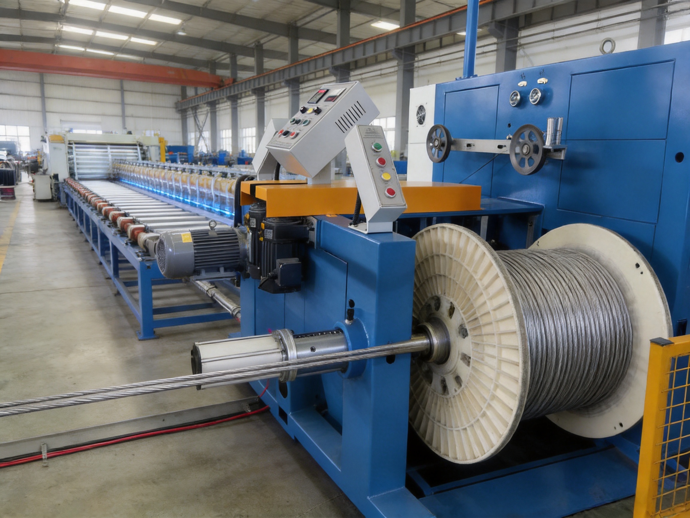
Spool changeover is a major factor in the productivity of an extrusion line. Whenever a spool reaches its target length, the full spool must be secured and removed, an empty spool must be positioned, and the cable lead must be attached or transferred. During this period, the upstream line may continue operating, reduce speed, or rely on an accumulator.
Any cable produced while the take-up is not yet operating at stable winding tension may require inspection, downgrading, or scrapping. The scrap length is approximately equal to the line speed multiplied by the time during which the changeover affects stable collection.
For example, at a line speed of 200 meters per minute, a 30-second transition can represent approximately 100 meters of potentially unstable material. Reducing the changeover period to 8 seconds can lower this length to approximately 27 meters. The exact result depends on the accumulator configuration and product specifications, but the relationship illustrates why automated spool handling can provide a significant return on investment.
Typical Changeover Sequence
The first stage is full-spool detection. A meter counter, encoder, length preset, or production management signal identifies that the programmed length has been reached. The machine sends a signal to the accumulator and line control system.
The second stage is cable cutting and tail securing. An automated cutter can separate the finished cable and secure the tail to prevent loose material from unwinding. Automated operation is faster and more consistent than manual tying.
The third stage is full-spool removal and empty-spool positioning. A turret or spool carriage can rotate or index the next empty spool into position. Turret systems may complete this operation in a few seconds, while a single-position machine requiring forklift exchange may need several minutes.
The fourth stage is lead attachment and acceleration. The cable lead is fixed to the new core, and the winding drive accelerates to match the line speed. Servo-driven systems can provide controlled acceleration while avoiding excessive tension spikes.
Yessjet can configure take-up equipment according to the required production rhythm. Applications with frequent spool changes and high line speeds may benefit from turret-style operation, while lower-speed lines may use a simpler spool arrangement that prioritizes flexibility and lower initial cost.
Mechanical Compatibility and Spool Interface Design
Winding quality depends not only on control software and motors but also on the mechanical relationship between the spool and the machine shaft. A mixed spool inventory can contain variations in bore diameter, keyway dimensions, flange concentricity, flange runout, and structural strength.
A spool bore that is only slightly larger than the shaft can allow eccentric rotation. This eccentricity produces a once-per-revolution tension ripple that may appear to be a control problem but cannot be eliminated through PID adjustment alone. The root cause is mechanical clearance between the shaft and spool.
Before production use, spool compatibility should be checked systematically. Bore diameter should be measured with a calibrated gauge. Keyway width and depth should match the shaft interface. Flange runout should be checked with a dial indicator, particularly after a spool has been dropped or struck. The spool’s maximum gross weight must include both the empty spool and the cable fill.
For precision take-up applications, a close-fit keyway is preferable to a loose general-purpose power transmission fit. Excessive clearance can permit small movements between the shaft and spool during acceleration or deceleration. These micro-slip events may create localized tension spikes and irregular cable placement.
The machine structure must also be designed for the combined weight and dynamic forces of the loaded spool. Traverse forces, acceleration torque, braking torque, and flange loading all influence bearing life and shaft deflection. Correct mechanical sizing supports long-term stability and reduces maintenance requirements.
Important Spool Inspection Points
Bore diameter should remain within the tolerance required by the shaft and adapter system.
Keyway geometry should prevent rotational slip while allowing practical spool installation and removal.
Flange runout should be controlled because excessive runout can create uneven layers and edge defects.
The spool should have sufficient rated capacity for the maximum cable fill weight and operating speed.
Damaged, distorted, or cracked spools should be removed from service.
Adapter sleeves should be used only when they maintain concentricity and secure mechanical locking.
Control Architecture for Extrusion Line Integration
When a motorized take-up machine is installed as part of a new extrusion line, the complete system can be engineered around a defined master-slave control structure. When it is retrofitted into an existing line, special attention must be given to the interaction between the haul-off and the take-up drive.
The haul-off is commonly the speed master. It establishes the production speed, while the extruder, cooling system, measurement devices, and take-up follow the line reference. If both the haul-off and take-up independently attempt to regulate cable speed, their control loops may work against each other.
For example, if the system detects a tension decrease, the haul-off may attempt to increase speed while the take-up simultaneously reduces speed. This opposing response can create oscillation, unstable dancer movement, and repeated tension variation. Such problems cannot be solved reliably by simply increasing or decreasing controller gain.
A common solution is to operate the take-up drive in torque-control mode while allowing the haul-off to remain the speed master. The take-up then supplies the winding torque corresponding to the target tension. Its rotational speed changes naturally as the spool diameter changes and as the upstream line determines cable speed.
In this architecture, the dancer position can be used as a trim signal that makes small adjustments to torque. It does not need to serve as the primary speed reference. This arrangement reduces loop conflict and creates a clearer division of control responsibilities.
Yessjet’s retrofit engineering process begins with an audit of the existing line. Engineers review the haul-off drive type, communication protocol, encoder signals, PLC structure, available input and output points, safety circuits, accumulator capacity, and line operating range. The integration plan then defines the speed reference, torque command, tension feedback, emergency stop behavior, fault communication, and spool change handshake.
This structured approach is an important advantage over equipment that is supplied as an isolated machine without considering the existing line. Proper integration reduces commissioning time, prevents avoidable production trials, and helps the customer achieve stable operation sooner.
Manufacturing Strengths and Engineering Capabilities
Shanghai Yessjet Precise Machinery Co., Ltd. was founded in 2002 in Shanghai with investment from Taiwan. The company’s development continued through Jiangsu Yessjet Precise Machinery Co., Ltd. in Yixing, Wuxi, in 2017. This background supports an engineering-oriented approach to wire and cable machinery, including extrusion lines, pay-off systems, take-up systems, coiling equipment, packaging machines, accessory equipment, and intelligent stacking solutions.
The company’s strength is not limited to assembling motors and frames. A high-quality take-up machine requires coordinated design across mechanical engineering, drive control, tension management, electrical integration, safety systems, and production application knowledge.
Application-Based Mechanical Design
The frame, shaft, spool support, traverse structure, and transmission system are selected according to cable size, spool mass, winding width, operating speed, and production environment. This avoids the limitations of one-size-fits-all equipment and allows the machine to be adapted to different customer requirements.
Drive and Control Engineering
Motor and drive selection is matched to the required torque range, acceleration profile, winding speed, and tension stability. Frequency-converted motors may provide an economical and robust solution for standard applications, while servo systems can be used where rapid response, precise positioning, and high-speed spool changeover are important.
Recipe-Based Operation
Product recipes can store cable-specific settings such as target length, tension, taper profile, traverse pitch, spool width, flange limits, acceleration, deceleration, and alarm thresholds. This improves repeatability and allows operators to change products with less manual adjustment.
Complete Line Integration
Because Yessjet supplies multiple categories of wire and cable machinery, the company can evaluate the take-up machine as part of a complete production process. This broader perspective is valuable when the customer requires coordination between pay-off, extrusion, cooling, diameter control, spark testing, haul-off, take-up, coiling, packaging, and stacking.
Manufacturing and Assembly Control
Reliable operation depends on accurate alignment, balanced rotating components, correct bearing installation, controlled electrical wiring, and systematic testing. Manufacturing and assembly procedures should include inspection of shaft concentricity, traverse travel, motor direction, guard operation, sensor signals, emergency stop circuits, and communication with the line control system.
Before shipment, the equipment can be checked through dry runs and functional tests. These tests help verify acceleration, braking, traverse reversal, tension response, spool positioning, alarm functions, and operator interface behavior. For customized machines, testing should also reflect the customer’s cable specification and spool design wherever practical.
Safety Features for Industrial Operation
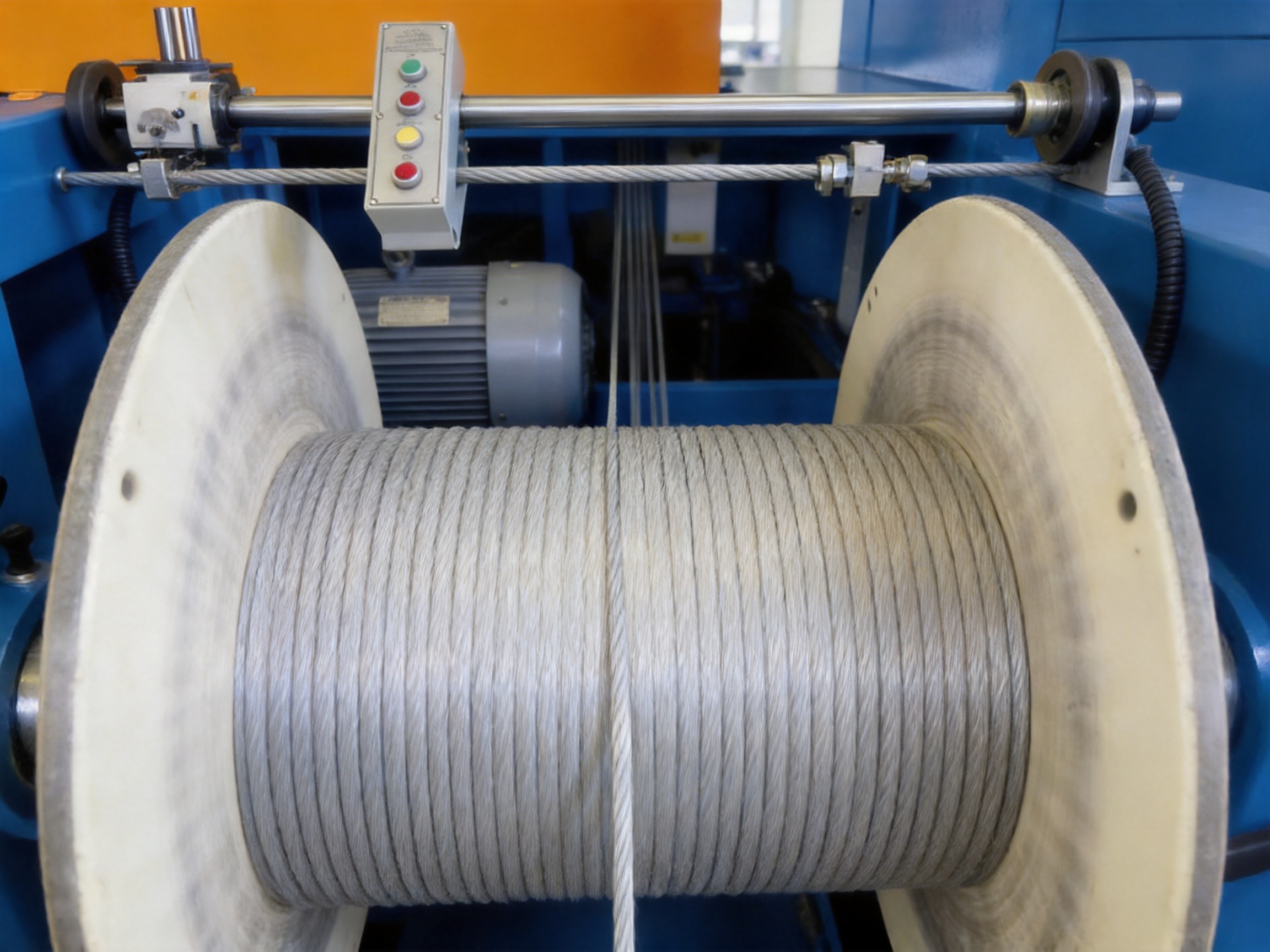
A take-up machine combines rotating shafts, moving traverses, heavy spools, electrical drives, and stored mechanical energy. Safety must therefore be incorporated into the machine design rather than treated as an operator responsibility alone.
Protective guards can limit access to rotating parts and pinch points. Door interlocks can prevent operation when a guard is open. Emergency stop devices should be accessible from the operator position and other relevant areas. The control system should also manage controlled stopping, fault indication, overload protection, and restart prevention.
Large spool handling requires special attention. The machine should provide stable support during spool loading and unloading, and the operating procedure should define maximum spool weight, lifting points, locking requirements, and safe clearance around the equipment.
Safety functions should be tested regularly. Operators should receive training on emergency stop use, spool installation, cable threading, fault recovery, and lockout procedures. Preventive maintenance should include inspection of guards, switches, brakes, couplings, bearings, cables, and safety labels.
Applications Across Wire and Cable Industries
Power Cable
Power cable often requires high-capacity spools and carefully controlled tension because insulation, shielding, armor, and jacket layers may be sensitive to compression. Taper tension and robust shaft design are particularly important for large filled spools.
Building Wire
Building wire production typically requires reliable high-speed collection, accurate length measurement, and clean layer formation. A programmable traverse system can produce compact spools that are easy to handle and pay off.
Communication and Data Cable
Communication and data cables may require low and stable tension to protect conductor geometry and insulation dimensions. Load-cell feedback and fine traverse adjustment can be beneficial for high-precision products.
Automotive Cable
Automotive cables are often produced in multiple sizes and constructions. Recipe management allows quick changeovers, while compact spool handling can support flexible production schedules.
Flexible and Multi-Core Cable
Flexible cables may have wider outer-diameter variation and more complex bending behavior. The take-up system should allow suitable tension, pitch, and reversal settings to prevent gaps or overlapping turns.
Armored Cable
Armored cable has increased mass, stiffness, and surface irregularity. The machine must be designed for the required load, and the traverse pitch should consider armor wire height and the actual outer profile.
Operating Procedure and Maintenance Recommendations
Before starting production, the operator should confirm that the correct spool is installed, mechanically locked, and suitable for the cable specification. The cable path should be checked for proper threading through guide rollers, dancer components, load cells, and the traverse guide.
The selected recipe should be verified against the production order. Important values include cable diameter, target length, spool width, winding direction, tension, taper ratio, traverse pitch, acceleration, and changeover mode.
During operation, the operator should monitor cable alignment, dancer position or tension feedback, spool rotation, traverse movement, drive load, alarms, and the condition of the cable surface. Unusual vibration, periodic tension fluctuation, edge buildup, or repeated pitch defects should be investigated promptly.
Daily maintenance may include cleaning cable dust from guides and sensors, checking guards and emergency stops, inspecting the spool locking system, and confirming that the cable path is free from contamination. Periodic maintenance may include lubrication, bearing inspection, coupling checks, electrical cabinet cleaning, sensor calibration, and verification of drive parameters.
Load cells should be calibrated according to the application and operating environment. Dancer systems should be checked for free movement, correct spring or pneumatic preload, and mechanical friction. Traverse mechanisms should be inspected for backlash, abnormal noise, and accurate reversal at both flange positions.
Spool runout should be checked when unexplained once-per-revolution tension variation appears. If the spool is eccentric, replacing or repairing the spool may be more effective than adjusting the controller.
How to Select the Correct Machine Configuration
The correct motorized take-up machine depends on more than the maximum cable diameter. A complete technical specification should include cable construction, outer diameter range, line speed, spool dimensions, maximum spool weight, winding length, required tension range, winding direction, changeover method, available floor space, and line communication requirements.
The customer should also identify whether the machine will operate as a standalone unit or as part of a complete extrusion line. A standalone machine may require its own speed reference and tension control. A line-integrated machine must exchange signals with the haul-off, accumulator, meter counter, and safety system.
The required level of automation should be determined from production volume and labor objectives. Manual spool loading may be sufficient for low-volume production. A turret, automatic cutter, accumulator handshake, or robotic spool handling system may be more appropriate for high-volume production with frequent changeovers.
Environmental conditions also matter. Dust, temperature, humidity, floor vibration, and available electrical power can influence cabinet design, sensor selection, cooling requirements, and maintenance planning.
Key Questions for Technical Specification
What is the minimum and maximum cable outer diameter?
What is the normal and maximum production line speed?
What are the empty and full spool dimensions?
What is the maximum loaded spool weight?
What tension range is required for each cable type?
Is a dancer or load-cell system more appropriate for the application?
Is taper tension required?
What level of traverse pitch accuracy is required?
How frequently will spool changes occur?
Is automatic cutting, tail securing, or turret exchange required?
Which PLC, drive, and communication standards are used on the existing line?
What safety standards and plant procedures must be followed?
Economic Benefits and Return on Investment
The financial value of a motorized take-up machine comes from several sources. Reduced cable scrap is often one of the most visible benefits. Stable winding lowers the risk of damaged insulation, crossed layers, and unusable spools. Faster changeover reduces downtime and increases the productive operating time of the extrusion line.
Automation also reduces the need for continuous manual guiding and spool intervention. Operators can supervise more than one machine or focus on quality inspection and process control. Reduced manual handling may lower ergonomic risks associated with lifting, tying, and managing long cable lengths.
Improved spool quality benefits downstream operations. Cable that is wound evenly pays off more smoothly, reducing interruptions during installation, cutting, rewinding, packaging, or further processing. Consistent spool presentation can also improve customer satisfaction and reduce complaints related to tangled or damaged product.
Energy efficiency may be improved through controlled acceleration, torque regulation, and reduced mechanical losses. The exact result depends on motor selection, line speed, spool mass, production schedule, and operating conditions, but a properly sized drive system avoids unnecessary overcapacity and inefficient braking.
For each customer, the return on investment should be calculated using actual production data. Important variables include line speed, spool change frequency, average scrap length, cable material cost, labor cost, downtime value, and the percentage of production requiring manual intervention.
Quality Assurance and Production Consistency
A motorized take-up machine contributes to quality assurance by making winding conditions repeatable. When tension, pitch, spool speed, and changeover timing are controlled, the resulting spool is less dependent on individual operator technique.
Quality records can include product recipe, production length, tension trend, drive load, alarm history, spool identification, and changeover time. These records support process analysis and help manufacturers identify the source of recurring defects.
Consistent winding also makes inspection easier. A spool with uniform layers allows operators to identify surface marks, diameter variation, printing defects, or insulation damage more quickly. It reduces the possibility that a defect will be hidden in a loose or crossed layer.
Where required, the machine can be integrated with diameter measurement, spark testing, meter counting, production data collection, and line-level traceability systems. These functions support a more complete quality management process from extrusion through final packaging.
Why Choose a Specialized Manufacturer
Purchasing a take-up machine from a supplier that understands wire and cable production provides advantages over buying a generic industrial winder. Cable products have specific requirements involving tension, bending radius, surface protection, spool geometry, and synchronization with continuous extrusion.
A specialized manufacturer can evaluate the complete material path and identify whether a defect originates in the take-up machine, spool, guide system, haul-off, or upstream process. This reduces the risk of solving a mechanical problem with unsuitable software adjustments.
Shanghai Yessjet Precise Machinery Co., Ltd. combines wire and cable machinery experience with application-oriented integration. Its product range includes wire and cable extrusion line equipment, fully automatic coiling and packaging equipment, intelligent robot stackers, coiling machines, motorized pay-off equipment, motorized take-up equipment, and accessory machinery.
This product range enables the company to support individual machine purchases as well as broader cable production turnkey solutions. The engineering team can consider how the take-up machine will interact with upstream and downstream equipment, helping customers build a more coordinated production system.
Customization is another important strength. Cable manufacturers may have non-standard spool dimensions, special tension requirements, unusual line layouts, multiple product ranges, or specific automation objectives. A configurable machine can be adapted to these conditions rather than forcing the customer to redesign the production process around a fixed standard.
Q&A: Motorized Take-Up Equipment Machine
What materials can the machine wind?
The machine is designed primarily for wires, power cables, communication cables, automotive cables, flexible cables, armored cables, and similar continuous products. The final configuration depends on cable diameter, material, stiffness, surface condition, spool dimensions, and production speed.
Why is tension control important?
Tension control prevents excessive stretching, jacket compression, loose winding, kinking, and tangling. It also helps protect conductor position and insulation performance. Stable tension is essential for producing compact and reliable cable spools.
What is taper tension?
Taper tension is a control strategy that reduces winding tension as the spool diameter increases. It helps limit the compressive force applied to inner cable layers on large spools. The correct taper profile depends on the cable material, spool geometry, and acceptable compression level.
Should a dancer or load cell be used?
A dancer provides buffering and can absorb short-term speed changes. A load cell measures tension more directly and can provide a faster feedback signal. The better choice depends on cable type, line speed, required accuracy, friction in the cable path, and the control architecture of the line.
Can the machine be added to an existing extrusion line?
Yes. Retrofit integration requires an assessment of the existing haul-off drive, PLC, communication protocols, available I/O, accumulator, safety circuit, and line speed control. A torque-controlled take-up working with a speed-master haul-off is often an effective architecture.
Can the machine use different spool sizes?
It can be configured for a specified range of spool dimensions. The shaft interface, spool bore, flange width, maximum diameter, keyway, and load rating must be verified. Recipe-based settings can help manage different spool and cable combinations.
How does automatic spool changing reduce scrap?
Automatic cutting, tail securing, spool indexing, and controlled acceleration shorten the period during which the line is producing cable without stable winding. A shorter transition generally reduces the amount of material that must be scrapped or downgraded.
How is traverse pitch selected?
Traverse pitch is based on cable outer diameter, dimensional tolerance, winding pattern, and spool width. For products with broad OD variation, real-time measurement can improve pitch control. The flange reversal profile must also be adjusted separately from the steady-state pitch.
What should be checked if the cable has periodic tension variation?
Possible causes include spool eccentricity, flange runout, loose shaft fit, keyway clearance, guide friction, sensor calibration, drive tuning, or mechanical imbalance. The spool and shaft interface should be inspected before making extensive controller adjustments.
Is the machine suitable for high-speed production?
High-speed suitability depends on cable diameter, spool size, tension requirement, motor rating, traverse speed, and changeover design. Servo acceleration, load-cell feedback, automatic spool exchange, and appropriate line integration can support demanding production conditions.
What information should be provided for a quotation?
Customers should provide cable diameter range, cable construction, line speed, spool dimensions, maximum loaded spool weight, required winding length, tension range, production layout, automation expectations, power supply, and communication requirements. Sample cable and spool information can further improve the technical proposal.
Conclusion
A motorized take-up equipment machine is a critical production asset for manufacturers seeking stable cable quality, reduced waste, improved line efficiency, and safer operation. Its performance depends on the coordinated control of winding torque, spool speed, traverse pitch, tension feedback, spool mechanics, and line communication.
Advanced functions such as taper tension, programmable traverse reversal, load-cell or dancer feedback, automatic spool changeover, recipe management, and torque-based line integration provide measurable advantages over basic winding systems. These functions help protect cable quality from the empty core to the full spool and allow the equipment to adapt to different products and production conditions.
Shanghai Yessjet Precise Machinery Co., Ltd. supports these requirements through specialized wire and cable machinery design, manufacturing, control engineering, retrofit integration, and complete production-line planning. Its motorized take-up equipment machines can be configured for different cable types, spool sizes, line speeds, and automation levels.
For manufacturers investing in a new extrusion line or upgrading an existing cable production system, selecting the take-up machine as part of the total process—not as an isolated winding device—can deliver better long-term results. Correct mechanical sizing, suitable tension architecture, reliable traverse control, and coordinated automation are the foundations of efficient and high-quality cable collection.
References
1. Cable Manufacturing Process Engineering: Principles of Extrusion, Cooling, Haul-Off, and Take-Up.
2. Industrial Web Handling and Tension Control: Dancer Systems, Load Cells, Torque Control, and Drive Integration.
3. ISO 286, Geometrical Product Specifications: ISO Code System for Tolerances on Linear Sizes.
4. Industrial Machinery Safety Principles: Guards, Interlocks, Emergency Stops, and Stored-Energy Control.
5. Practical Guidelines for Cable Spool Design, Flange Runout, Bore Tolerances, and Load Rating.
6. Variable-Frequency Drive and Servo-Control Applications in Continuous Material Processing.
7. Wire and Cable Production Quality Control: Tension Stability, Diameter Management, Layer Formation, and Scrap Reduction.