LANGUAGE
 中文简体
中文简体 русский
 Français
 Español
 Português
 عربى
عربى
Content
- 1 What a Complete Wire and Cable Extrusion Line Includes
- 2 Core Advantages of the Extrusion System
- 3 Precise Temperature Control for Stable Polymer Processing
- 4 PLC-Based Line Coordination
- 5 Pay-Off and Conductor Handling Performance
- 6 Extrusion, Crosshead, and Die Operation
- 7 Cooling and Dimensional Stabilization
- 8 Continuous Diameter Measurement and Process Feedback
- 9 Haul-Off and Tension Control
- 10 Ink Printing and Product Identification
- 11 Take-Up, Winding, and Finished Cable Handling
- 12 Integration with Automatic Coiling and Packaging Equipment
- 13 Robot Stacking and Factory Automation
- 14 Manufacturing Strengths and Engineering Approach
- 15 Retrofitting Existing Cable Extrusion Lines
- 16 Advantages Compared with Less Integrated Equipment
- 17 Operational Efficiency and Cost Control
- 18 Recommended Quality Checks During Production
- 19 Maintenance Practices for Long-Term Reliability
- 20 Applications Across Multiple Cable Industries
- 21 Q&A: Wire and Cable Extrusion Line Selection and Operation
- 21.1 What is the purpose of a Wire And Cable Extrusion Line?
- 21.2 Which materials can the line process?
- 21.3 How do I choose the correct extruder model?
- 21.4 What does the G or S model designation mean?
- 21.5 Why is screw design important?
- 21.6 Can the line produce both insulated wire and sheathed cable?
- 21.7 What is the function of the diameter measuring instrument?
- 21.8 How can wall-thickness eccentricity be controlled?
- 21.9 Why are two cooling stages used?
- 21.10 Can automatic coiling be added later?
- 21.11 What are the benefits of a motorized pay-off?
- 21.12 Is the line suitable for factory automation?
- 21.13 Can an older extrusion line be upgraded?
- 21.14 What information is needed for a quotation?
- 22 Why Choose a Customized Production Solution
- 23 Conclusion
- 24 References
- 25 Product: Wire And Cable Extrusion Line
Wire and cable manufacturing demands a production system that can combine stable extrusion, accurate diameter control, reliable cooling, controlled tension, high-speed take-up, and efficient finished-product handling. A modern Wire And Cable Extrusion Line brings these functions together in one coordinated manufacturing process. Instead of treating the extruder, cooling section, haul-off, printing equipment, coiler, and take-up machine as independent units, an integrated line synchronizes them to maintain product quality from conductor pay-off to final reel or coil.
Shanghai Yessjet Precise Machinery Co., Ltd. develops and supplies wire and cable machinery for manufacturers that need dependable production performance, flexible material processing, and scalable automation. Its Wire And Cable Extrusion Line is designed for the continuous insulation or sheathing of electrical wires and cables using materials such as PVC, PE, LSZH, Teflon, Nylon, and related thermoplastic compounds. The available configuration can be adapted to different conductor sizes, finished diameters, line speeds, output requirements, and packaging methods.
The line is suitable for manufacturers producing building wire, control cable, power cable, automotive wire, communication cable, appliance wire, industrial cable, and other insulated conductors. Its modular architecture also allows customers to select a basic extrusion configuration and later add automatic coiling, intelligent stacking, advanced inspection, or upgraded control functions as production requirements develop.
What a Complete Wire and Cable Extrusion Line Includes
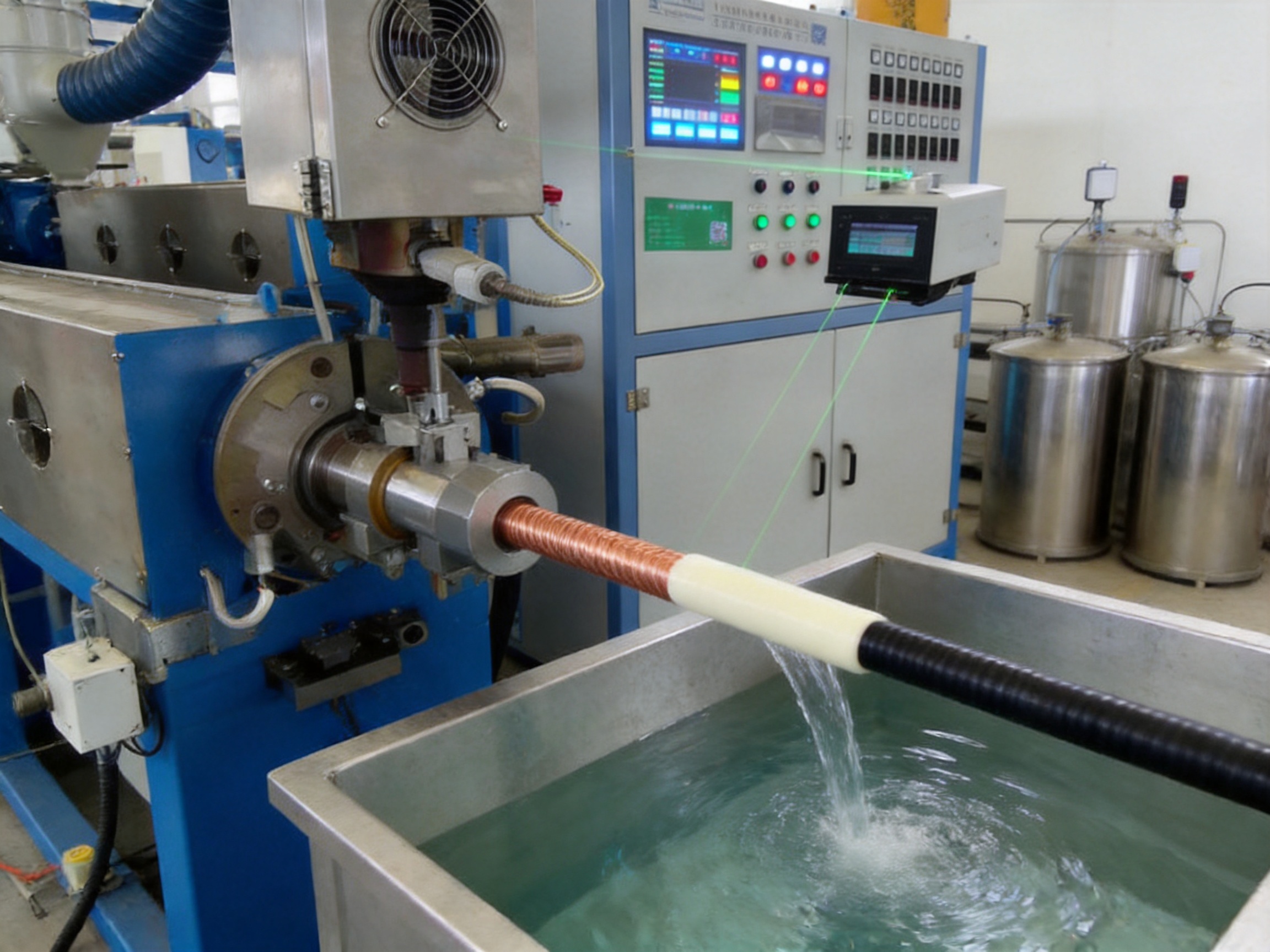
A cable extrusion line is a sequence of machines that transforms bare conductor into a finished insulated or sheathed product. Each unit affects the next stage. If the pay-off releases the conductor unevenly, the extrusion head may receive fluctuating tension. If the cooling water temperature is unstable, the cable surface may deform. If the haul-off speed changes suddenly, the insulation wall thickness can move outside the required tolerance. For this reason, line integration is just as important as the performance of the individual machines.
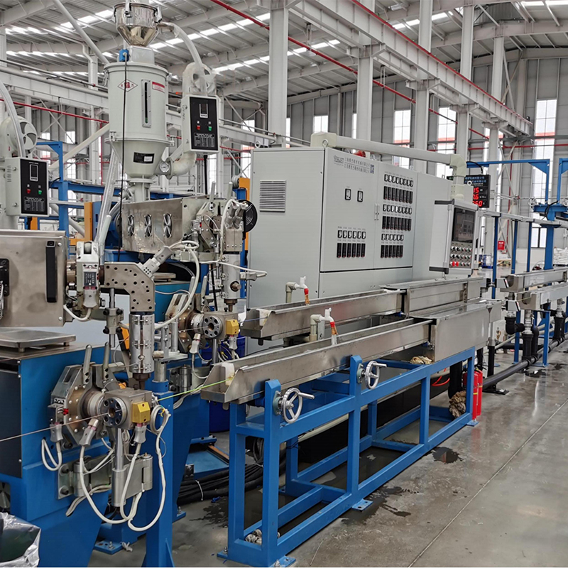
A typical Yessjet configuration consists of the following primary sections:
- Motorized or controlled pay-off equipment for stable conductor unwinding.
- A straightening stand to remove bending and improve conductor alignment.
- An extrusion machine with a material-specific screw and barrel design.
- A crosshead and die system for concentric insulation or sheathing.
- A main electrical control and operation box for coordinated line management.
- Diameter measuring equipment for continuous product monitoring.
- A pre-cooling water tank for initial cooling after extrusion.
- An ink printing machine for model numbers, dates, batch information, or markings.
- A main cooling water tank for final dimensional stabilization.
- A dual-wheel take-up or caterpillar haul-off for controlled product movement.
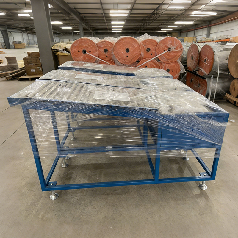
- A winding and storage rack for temporary cable accumulation.
- A tension control rack for regulating the cable path.
- A dual-axis take-up machine for winding finished cable onto reels.
- Optional automatic coiling, packaging, palletizing, and robotic stacking equipment.
This arrangement makes the line suitable for continuous production rather than intermittent manual processing. The conductor can travel through the line at a controlled speed while the extruder meters polymer, the cooling system stabilizes the insulation, the printer applies identification, and the take-up system prepares the finished cable for storage or shipment.
Wire And Cable Extrusion Line
Core Advantages of the Extrusion System
Material-Specific Screw and Barrel Configurations
The screw and barrel are the central processing components of an extrusion machine. Their geometry determines how efficiently polymer is conveyed, melted, mixed, pressurized, and delivered to the die. A single universal screw may be able to process several materials, but it will not necessarily provide the best balance of output, melt uniformity, and thermal control for every compound.
The extrusion systems supplied by Yessjet can be configured for different plastic materials, including PVC, PE, LSZH, Teflon, and Nylon. This material-oriented approach is important because these polymers have different melting behavior, viscosity, thermal sensitivity, and processing windows. PVC compounds generally require careful control of shear and residence time. Polyethylene requires consistent melting and stable pressure. LSZH materials may need special attention to thermal loading and mixing. Fluoropolymers such as Teflon typically require specialized processing conditions and temperature-resistant components.
The screw data shown in the product range use L/D ratios generally suited to cable insulation and sheathing work. Models are available with screw diameters from 40 mm to 120 mm, allowing customers to match the machine to their intended output. Smaller extruders are appropriate for fine wires and lower production volumes, while larger models support heavier cable applications and higher polymer throughput.
Imported Screw and Barrel Manufacturing Quality
The product specification identifies imported barrel and screw components from Taiwan as a key feature. High-quality screw and barrel components contribute to stable conveying, predictable pressure development, and improved resistance to wear. Consistent internal dimensions also help reduce fluctuations caused by irregular clearance between the screw and barrel.
For cable production, dimensional stability is particularly important. The insulation layer may be thin, and small variations in melt delivery can affect finished diameter and minimum wall thickness. A properly manufactured screw and barrel pair reduces unnecessary surging and gives the control system a more stable process to regulate.
The mechanical condition of these components also influences energy consumption. Excessive wear can reduce conveying efficiency, increase leakage over the screw flights, and force operators to raise screw speed or temperature to maintain output. A well-matched screw and barrel system helps the extruder achieve its rated capacity with more consistent operating conditions.
High Extrusion Capacity Across Multiple Models
The range includes G and S configurations across several screw diameters. Depending on the model and material, the nominal maximum extrusion capacity extends from approximately 24 kg per hour to 600 kg per hour. Finished cable diameter ranges begin at approximately 0.8 mm for smaller models and extend to approximately 40 mm for larger systems.
This range gives cable manufacturers a practical method of selecting equipment according to product family. A producer of small appliance wire may require an EX-40G or EX-50G system, while a manufacturer of medium-sized industrial cables may select an EX-70, EX-80, or EX-90 model. Large conductors and thick sheaths may require the greater output and drive power of an EX-100 or EX-120 machine.
| Model | Screw Diameter | L/D Ratio | Maximum PVC Capacity | Maximum LDPE Capacity | Maximum LSNH Capacity | Finished Diameter | Drive Motor |
| EX-40G | 40 mm | 26:1 | 120 kg/h | 24 kg/h | 14 kg/h | 0.8–3 mm | 11 kW |
| EX-50S | 50 mm | 26:1 | 120 kg/h | 75 kg/h | 35 kg/h | 1–6 mm | 18.5 kW |
| EX-60S | 60 mm | 26:1 | 120 kg/h | 120 kg/h | 60 kg/h | 2–8 mm | 30 kW |
| EX-70S | 70 mm | 26:1 | 120 kg/h | 160 kg/h | 95 kg/h | 3–15 mm | 37 kW |
| EX-80S | 80 mm | 26:1 | 110 kg/h | 250 kg/h | 130 kg/h | 5–20 mm | 45 kW |
| EX-90S | 90 mm | 26:1 | 110:1 | 320 kg/h | 180 kg/h | 8–25 mm | 55 kW |
| EX-100S | 100 mm | 25:1 | 100 kg/h | 450 kg/h | 240 kg/h | 10–30 mm | 75 kW |
| EX-120S | 120 mm | 25:1 | 100 kg/h | 600 kg/h | Not specified | 15–40 mm | 110 kW |
Actual output depends on material formulation, conductor size, insulation thickness, screw speed, die design, cooling conditions, and operating stability. The capacity figures should therefore be used as selection references rather than guaranteed production values for every product specification.
Precise Temperature Control for Stable Polymer Processing
Temperature management is one of the most important factors in cable extrusion. The polymer must be heated sufficiently to melt and flow through the crosshead, but it must not be overheated or exposed to excessive shear heat. Inconsistent thermal conditions can cause surface roughness, bubbles, discoloration, gels, poor adhesion, or unstable wall thickness.
The line uses logical tracer-type temperature controllers identified in the product information as RKC controllers made in Japan, together with SSR electrical circuits. The stated temperature deviation is approximately plus or minus 2 degrees Celsius. This level of control helps maintain a consistent processing window across the barrel and die zones.
Programmable temperature control also supports faster product changeovers. Operators can store or record temperature settings for different polymer grades and cable sizes. When a new product is scheduled, the line can be adjusted systematically rather than relying only on manual memory. Consistent recipes reduce startup scrap and make production results less dependent on individual operator experience.
Temperature Zones and Material Behavior
Modern extrusion systems generally divide the barrel into multiple controlled zones, followed by separate crosshead and die zones. The purpose is to guide the polymer through a controlled heating and melting sequence. The feed zone must accept solid pellets or compound without premature bridging. The compression zone must promote gradual melting. The metering zone must deliver a homogeneous melt at a stable pressure. The die zone must maintain suitable viscosity as the material enters the crosshead.
For HDPE, a gradually rising temperature profile can encourage controlled melting and reduce feed problems. Flexible PVC often benefits from a flatter profile that limits excessive shear heat. LSZH compounds require careful adjustment because they may have a narrower processing window than standard polyethylene or PVC. These are starting principles rather than fixed recipes. Actual settings should be confirmed through melt pressure, surface quality, diameter measurements, and material supplier recommendations.
| Material | Feed Zone Reference | Compression Zone Reference | Metering Zone Reference | Die Zone Reference |
| HDPE | 160–175°C | 190–200°C | 210–220°C | 215–225°C |
| Flexible PVC | 150–160°C | 165–175°C | 170–180°C | 175–185°C |
| XLPE | 100–115°C | 120–130°C | 125–135°C | 130–140°C |
| LSZH | 155–165°C | 170–180°C | 175–185°C | 180–190°C |
The correct settings depend on the exact compound, filler content, color masterbatch, conductor temperature, screw geometry, and production speed. A stable control system gives the operator the foundation needed to optimize those factors without large temperature swings.
PLC-Based Line Coordination
The system circuit is controlled by a programmable logic controller. PLC control is a major advantage over traditional relay-based systems because it allows the main machines to work as one coordinated production line. Start-up, acceleration, normal production, fault handling, and shutdown can be sequenced more systematically.
A PLC can coordinate extruder speed, haul-off speed, cooling functions, printing, take-up, and safety interlocks. For example, the line can prevent the haul-off from running before the cooling system is ready, or stop material feeding when a downstream take-up fault occurs. Such interlocks reduce the risk of cable accumulation, uncontrolled tension, or mechanical damage.
The control architecture can also support recipe management, alarm monitoring, production counters, and communication with optional equipment. Spare input and output capacity is valuable when a customer later adds a coiler, packaging machine, laser gauge, or robotic palletizer. Planning these interfaces during the initial design is normally more economical than rebuilding the control cabinet after installation.
Operator-Friendly Production Control
The main electrical control and operation box provides a centralized interface for line operation. Operators can monitor process values and adjust important settings from a defined control station rather than moving between separate machines. Clear control logic is especially useful during product changeovers, troubleshooting, and controlled startup.
Important operating parameters may include screw speed, haul-off speed, line speed, temperature zone settings, cooling water status, printing speed, take-up tension, meter count, and alarm status. By bringing these functions together, the operator can make coordinated adjustments. This helps prevent a common problem in less integrated lines, where one machine is changed without considering its effect on the rest of the process.
Pay-Off and Conductor Handling Performance
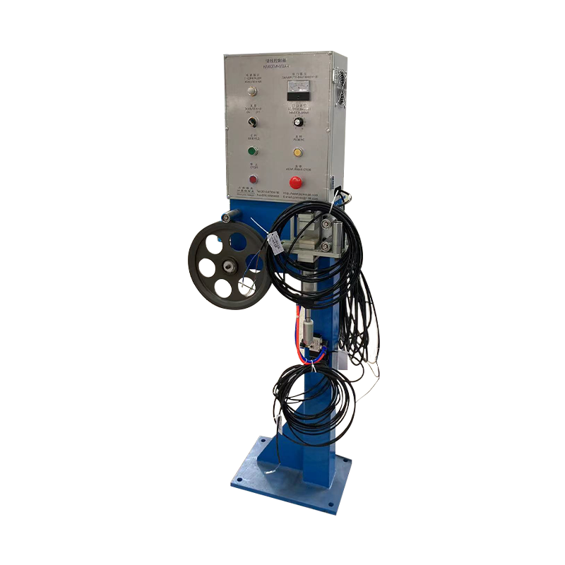
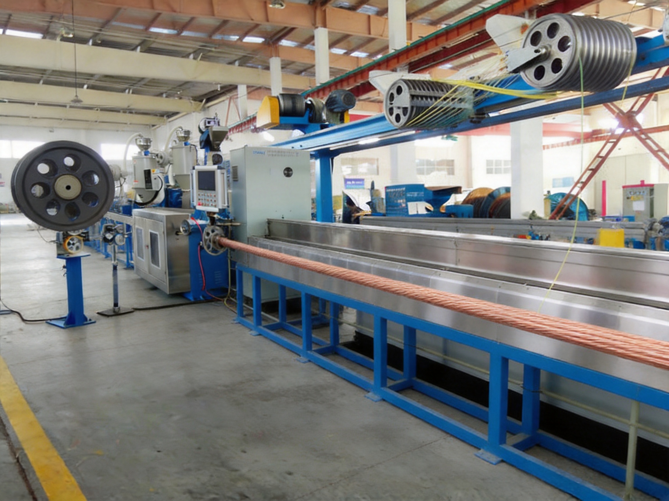
The pay-off section is the first mechanical stage of the line and has a direct influence on the stability of the entire process. A motorized pay-off equipment machine releases conductor from a coil or reel while maintaining a controlled supply path. The purpose is not merely to unwind material, but to prevent sudden tension changes, snarling, back tension, and uncontrolled reel rotation.
Different conductors require different handling conditions. Solid copper wire, stranded copper conductor, tinned conductor, aluminum conductor, and fine-wire constructions vary in flexibility and tensile behavior. A controlled pay-off can be adjusted to match the conductor structure and reel weight. Stable unwinding also helps the straightening stand and extrusion crosshead receive a more centered and predictable conductor.
The straightening stand removes bends created during previous conductor processing or reel storage. Straightening is essential because a curved conductor can move off-center inside the crosshead. If the conductor is not centered, insulation thickness may be heavier on one side and thinner on the other. Good conductor alignment therefore supports concentricity and reduces the burden on die-centering adjustments.
Extrusion, Crosshead, and Die Operation
Inside the extruder, solid polymer is conveyed along the screw, heated, mixed, and pressurized. The melt then travels to the crosshead, where it is distributed around the conductor. The die determines the external shape and contributes to the final insulation geometry. The relationship between conductor diameter, die dimensions, melt pressure, line speed, and haul-off speed determines the draw-down and finished wall thickness.
For high-quality cable production, the melt should reach the crosshead with minimal pressure fluctuation. Pressure surges can create periodic diameter variation or surface irregularities. A suitable screw design, stable temperature profile, clean material supply, and properly maintained screen pack all contribute to smoother extrusion.
Die centering is also important. A cable may have a correct average outside diameter while still showing excessive eccentricity. Therefore, operators should check both overall diameter and wall thickness at multiple positions around the cable. When required, ultrasonic or capacitance-based inspection can complement the standard laser diameter gauge.
How Screw Geometry Affects Product Quality
Screw diameter is only one part of screw design. L/D ratio, compression ratio, flight pitch, mixing elements, barrier sections, and metering geometry influence polymer processing. A longer L/D ratio can provide additional residence time and mixing, but it can also increase shear heating. The ideal arrangement depends on the polymer and the target output.
Materials with different viscosity curves do not respond identically to the same RPM. A screw optimized for PVC may generate a different melt temperature and pressure pattern when used with PE or LSZH. For this reason, Yessjet’s engineering approach emphasizes selecting screw geometry according to the compound family, target output, and cable application rather than treating one configuration as suitable for all products.
This approach can improve melt homogeneity and reduce defects that are sometimes incorrectly attributed only to die centering or tension. If the polymer is not consistently mixed or melted before entering the crosshead, downstream adjustments cannot fully correct the problem.
Cooling and Dimensional Stabilization
Freshly extruded insulation leaves the die at an elevated temperature and remains soft until sufficient heat has been removed. The cooling system must reduce the temperature gradually and evenly while maintaining the cable shape. The line includes a pre-cooling water tank followed by a main cooling single-layer water tank.
The pre-cooling stage provides initial heat removal close to the extrusion head. This helps prevent the hot polymer from remaining soft for too long or contacting downstream components before it has adequate strength. The main water tank continues cooling and stabilizes the finished diameter before printing, haul-off, and take-up.
Water temperature, flow, cleanliness, tank alignment, and cable immersion all affect cooling performance. If cooling is insufficient, the cable may deform under haul-off pressure. If the water is excessively cold or poorly distributed, internal stress may develop in some materials. Consistent water circulation and regular maintenance are therefore necessary for repeatable results.
The cooling length should match the material, cable diameter, extrusion speed, and insulation thickness. Larger cables and thicker sheaths require more time to solidify. The line layout can be configured to provide the required cooling distance while maintaining a practical factory footprint.
Continuous Diameter Measurement and Process Feedback
An outer diameter measuring instrument provides continuous information about the cable as it moves through the line. Unlike occasional manual checks, continuous measurement can identify gradual drift, sudden changes, and periodic variation. The operator can use this information to adjust extruder output or haul-off speed before large quantities of material are produced outside specification.
Laser gauges are commonly installed after the cooling section because the cable must be sufficiently stable for accurate measurement. Depending on the equipment configuration, the measurement can be connected to the PLC and used in a closed-loop control strategy. The system may regulate line speed, screw speed, or both to maintain the target diameter.
Closed-loop control is particularly useful at steady production speed. However, it should not be regarded as a replacement for good mechanical alignment or correct process setup. A diameter gauge generally measures the outside dimension and may not detect wall thickness eccentricity. Crosshead alignment, conductor centering, melt pressure stability, and die condition must still be managed correctly.
There is also a process delay between the die exit and the measuring point. If the cooling tank is long, a disturbance may reach the gauge several seconds after it occurs at the crosshead. The control system must therefore use appropriate response limits and deadband settings. Excessive correction can produce oscillation, causing more variation than the original disturbance.
Haul-Off and Tension Control
The dual-wheel take-up or caterpillar haul-off pulls the cable through the line at a controlled speed. Its work affects not only production rate but also insulation wall thickness. The relationship between extruder output and haul-off speed determines how much the molten insulation is drawn down before solidification.
If haul-off speed increases while extrusion output remains constant, the insulation may become thinner and the outside diameter may decrease. If haul-off speed decreases, the insulation may become thicker and the cable may accumulate in the cooling section. Stable synchronization is therefore essential.
Tension must be managed carefully for both the product and the conductor. Excessive belt pressure can mark soft insulation materials such as silicone or flexible TPU. Excessive line tension can elongate fine stranded conductors and alter their lay length or electrical resistance. Insufficient tension can cause sagging, unstable printing, poor meter counting, or irregular take-up.
A suitable caterpillar configuration considers cable diameter, surface hardness, compound stiffness, belt contact length, and production speed. Wider belt pads and lower clamping force may be suitable for softer materials, while larger and more rigid cables may require a different pressure setting.
The tension control rack and dancer system help stabilize the line during normal operation and speed transitions. Feedback from pay-off and take-up sections can maintain a defined tension window during acceleration, deceleration, reel changes, and shutdown. This is an important advantage over simple systems that rely on manual brake adjustment alone.
Ink Printing and Product Identification
The integrated ink printing machine can apply model numbers, dates, standards, batch codes, company information, or other identification marks to the cable surface. Clear marking supports product traceability, inventory management, installation work, and quality control.
Printing must be synchronized with line speed. If the cable speed changes but the printer does not follow the change, the character spacing may become inconsistent or the print may blur. The PLC and line encoder can provide the coordination required for stable marking across a range of production speeds.
Printing performance also depends on surface temperature, cleanliness, ink selection, nozzle alignment, and cooling effectiveness. The cable should normally be sufficiently cooled before printing so the mark remains sharp and resistant to handling. Operators should verify adhesion and legibility during startup and after material or speed changes.
Take-Up, Winding, and Finished Cable Handling
After cooling, measurement, printing, and haul-off, the cable must be collected without introducing damage or tension variation. The dual-axis take-up machine winds the product onto cable reels. A two-axis arrangement supports continuous production and efficient reel changeover, depending on the specific configuration.
Take-up control must match the changing reel diameter. As the reel fills, the rotational speed must be adjusted to maintain the required surface speed. If the winding speed is not synchronized, the cable may become loose, overlap incorrectly, or experience excessive tension. The winding and storage rack can provide temporary accumulation during transitions and help isolate upstream and downstream speed changes.
Good winding quality is important for transport, storage, and later installation. A correctly wound reel reduces the risk of tangling, crushing, crossed layers, and cable memory problems. For products supplied in coils rather than reels, an automatic coiling machine can create consistent coil diameter, length, and shape while reducing manual handling.
Integration with Automatic Coiling and Packaging Equipment
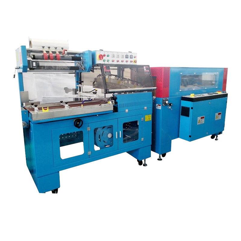
Automatic coiling is an important productivity improvement for small- and medium-diameter wires. Manual coiling can become a bottleneck when extrusion speeds exceed the operator’s ability to measure, cut, form, and transfer coils. An automatic coiling machine receives cable at a controlled speed, forms it into a defined coil, and prepares it for tying, taping, labeling, or packaging.
Successful integration requires more than placing a coiler at the end of the line. The extrusion control system must provide accurate meter counting, a dependable cut signal, and a coordinated transfer sequence. During coil changeover, cable slack must be controlled so that it does not accumulate between the cutter and the new coil core. The coiler must also communicate its ready, running, full, fault, and changeover status to the main PLC.
Yessjet’s line architecture can be planned with future end-of-line automation in mind. Spare I/O capacity, pre-wired terminal points, and documented signal maps can simplify the later addition of coiling, taping, packaging, or robotic palletizing equipment. This forward-compatible design helps customers avoid replacing the complete control system when production volumes eventually justify automation.
Packaging and Labeling Options
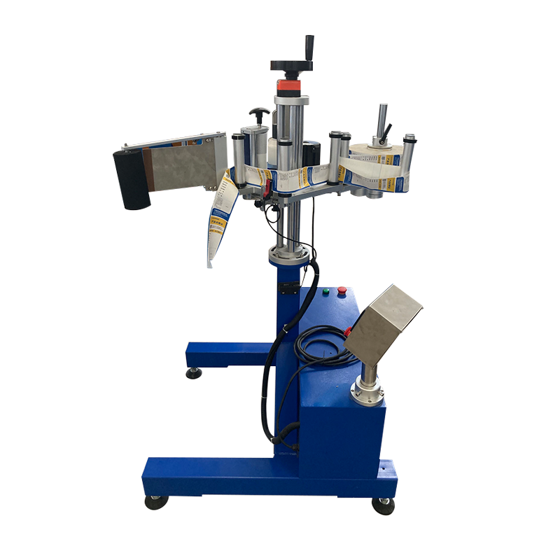
Finished coils can be combined with automatic taping, strapping, bagging, labeling, and counting functions. The appropriate solution depends on the coil length, cable diameter, packaging material, shipping requirements, and customer preferences. Standardized packaging improves handling efficiency and gives the finished product a more consistent appearance.
Packaging automation also improves workplace safety by reducing repetitive lifting and manual cable handling. Operators can supervise several stages of production instead of repeatedly forming and moving heavy coils. This can increase labor efficiency while allowing personnel to focus on inspection, material preparation, and process control.
Robot Stacking and Factory Automation
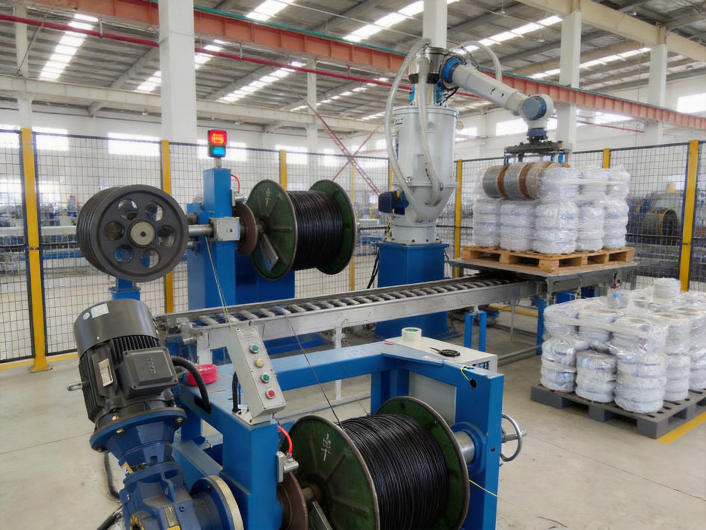
When cable coils or reels are produced at high volume, intelligent robot stacker equipment can organize finished units on pallets. Robotic stacking can position products according to a programmed pattern, maintain pallet stability, and reduce the risk of manual handling damage.
The robot may receive information about product type, coil size, package count, and pallet pattern from the line control system. This enables mixed production schedules and reduces the need for manual sorting. Sensors can verify package presence and pallet position before the robot begins a movement sequence.
Automation is especially valuable when the extrusion line operates continuously for long shifts. Without automated stacking, production may need to slow down while operators clear completed coils or reels. A coordinated end-of-line system allows the extruder to operate closer to its intended capacity.
Yessjet’s product range includes intelligent robot stackers, fully automatic coiling packaging equipment, accessory equipment, and motorized pay-off and take-up machines. These products can be combined into a complete cable production solution rather than purchased as unrelated machines from different suppliers.
Manufacturing Strengths and Engineering Approach
Application-Based Configuration
A major strength of an experienced cable machinery manufacturer is the ability to configure the line around the customer’s actual product. The correct system depends on conductor material, conductor size, insulation or sheath compound, finished diameter, wall thickness, required line speed, reel dimensions, factory layout, and packaging method.
Yessjet’s engineering process can evaluate polymer viscosity, processing temperature, output requirements, and line speed before specifying screw geometry and auxiliary equipment. This avoids the limitations of a one-size-fits-all machine. A customer producing flexible PVC building wire has different needs from a customer producing LSZH industrial cable or fluoropolymer-insulated high-temperature wire.
Integrated Mechanical and Electrical Design
Mechanical performance and electrical control must be designed together. The extruder may have sufficient output, but the line will not achieve its potential if the haul-off, cooling, pay-off, or take-up cannot maintain the required speed and tension. Similarly, precise sensors cannot compensate for poor alignment or worn mechanical components.
An integrated design allows the PLC, drives, sensors, temperature controllers, haul-off, take-up, and optional automation to exchange information. This reduces the number of manual interventions and makes fault diagnosis more systematic. It also enables the line to be expanded later with diameter control, production data collection, or robotic handling.
Quality-Oriented Assembly and Commissioning
Manufacturing a cable extrusion line involves machining, component inspection, electrical assembly, wiring, software configuration, mechanical alignment, and trial operation. Each stage contributes to final reliability. The screw and barrel must be correctly matched. The crosshead must be aligned with the conductor path. Water tanks must be positioned accurately. Sensors must be installed where they can measure stable process conditions.
During commissioning, the line should be tested through startup, normal operation, speed changes, emergency stops, material changes, reel changes, and controlled shutdown. Operators should receive guidance on temperature setting, tension adjustment, cooling management, die changes, cleaning, lubrication, and preventive maintenance.
Retrofitting Existing Cable Extrusion Lines
Not every manufacturer needs a complete new line. Many existing extrusion lines remain mechanically serviceable but use obsolete relay controls, analog temperature controllers, or outdated drives. Targeted modernization can improve operation while retaining valuable mechanical equipment.
Potential high-value retrofit projects include replacing the PLC, adding a touchscreen HMI, installing recipe management, upgrading to closed-loop diameter control, and adding servo-driven haul-off with tension feedback. Digital PID temperature controllers with auto-tuning can replace older analog units. Modern variable-frequency drives can improve speed control, diagnostics, and braking performance.
However, retrofit decisions must begin with a mechanical inspection. A control upgrade cannot compensate for severe screw wear, a damaged barrel, gearbox backlash, frame distortion, or a misaligned crosshead. Yessjet’s retrofit evaluation process can include screw and barrel wear assessment, gearbox testing, thermal imaging of heater performance, and a control-system audit.
| Assessment Area | Purpose | Typical Upgrade or Decision |
| PLC and control cabinet | Determine reliability, spare-part availability, and automation capability | Replace obsolete PLC, wiring, or control modules |
| Temperature control | Identify unstable or inaccurate heating zones | Install digital PID controllers and improved sensors |
| Extruder screw and barrel | Measure wear and conveying efficiency | Retain, repair, or replace processing components |
| Gearbox and drive | Check backlash, noise, lubrication, and load performance | Upgrade drive or repair mechanical transmission |
| Haul-off and tension | Evaluate speed stability and conductor stress | Add servo control, dancer feedback, or new belts |
| Diameter measurement | Determine whether quality can be monitored continuously | Add laser gauge or wall-thickness inspection |
| End-of-line automation | Check communication and space for coiling or stacking | Add signal interfaces and automated handling |
A structured evaluation can prevent customers from investing in controls for a mechanical platform that will require complete replacement soon. It also helps prioritize improvements according to production value rather than replacing every component unnecessarily.
Advantages Compared with Less Integrated Equipment
Compared with basic extrusion equipment assembled from disconnected machines, an integrated line offers better coordination between process stages. The key advantages include stable speed synchronization, centralized monitoring, consistent temperature control, improved tension management, and easier expansion.
Some low-cost systems may use generic screws, manual temperature controls, simple brake pay-offs, or independent take-up drives. These arrangements can reduce initial purchase price but may increase operator dependence and production variation. They may also create difficulties when adding diameter gauges, coilers, packaging equipment, or factory data systems later.
The Yessjet solution emphasizes configurable components and line-level control. Customers can select a suitable screw diameter and drive motor, specify the processing material, and integrate auxiliary equipment according to their product requirements. The result is a system that can be optimized for both current production and future automation.
Another advantage is the ability to address the complete production workflow. The supplier’s portfolio includes extrusion machines, coiling machines, motorized pay-off equipment, motorized take-up equipment, accessory equipment, packaging systems, and intelligent robot stackers. This can simplify technical communication, installation planning, spare-parts coordination, and after-sales support.
Operational Efficiency and Cost Control
Production efficiency is not determined only by maximum extrusion capacity. A line that frequently stops for manual adjustments, reel changes, unstable temperature, or cable handling may produce less saleable cable than a slightly slower but more stable line. The complete system should therefore be evaluated through uptime, startup waste, changeover time, labor requirements, energy consumption, and finished-product quality.
Accurate temperature control reduces the risk of producing material with surface defects or poor insulation properties. Stable pay-off and haul-off tension reduce conductor damage and wall-thickness variation. Continuous diameter measurement helps identify drift early. Automatic coiling and stacking reduce labor bottlenecks. Together, these functions can improve the proportion of production that meets specification.
Recipe-based operation can shorten changeovers between cable sizes or materials. When settings are documented and repeatable, operators can return to proven conditions instead of developing every product from the beginning. Preventive maintenance also becomes easier when wear points, alarms, and process trends are monitored systematically.
Recommended Quality Checks During Production
A professional production program should include checks at startup, during steady operation, after a material change, and before shipment. Typical checks include conductor diameter, insulation thickness, outer diameter, eccentricity, surface appearance, marking quality, spark-test performance, tensile properties, elongation, and electrical resistance.
The outer diameter gauge provides continuous dimensional information, but periodic manual or laboratory checks remain useful for verification. Wall thickness should be inspected around the cable circumference where the product specification requires concentricity. Electrical tests should confirm that the insulation provides adequate resistance and dielectric performance.
Operators should also monitor melt pressure, barrel temperature, motor load, screw speed, haul-off speed, cooling water temperature, and take-up tension. Trends are often more informative than isolated readings. A gradual increase in motor load may indicate material contamination, screen blockage, or screw and barrel wear. A periodic diameter pattern may suggest mechanical vibration, drive fluctuation, or an issue with material feeding.
Maintenance Practices for Long-Term Reliability
Preventive maintenance protects both product quality and equipment availability. The extrusion screw and barrel should be inspected according to operating hours, material abrasiveness, and production conditions. Screen packs, filters, die components, and crosshead passages should be cleaned before contamination affects the product.
Temperature sensors and heaters should be checked for correct response. A failed sensor can cause a zone to overheat or remain below the required processing temperature. Water tanks should be cleaned to prevent deposits and maintain efficient heat transfer. Pumps, valves, hoses, and cooling circuits should be inspected for leaks and flow restrictions.
Pay-off brakes, dancer rolls, belts, bearings, and take-up mechanisms require regular inspection. Misaligned rollers can create unnecessary cable tension or surface marks. The printer should be cleaned and calibrated to maintain legible marking. Automated coilers and robots require checks of sensors, grippers, cutting units, safety devices, and programmed motion sequences.
Maintenance records should include dates, operating hours, observed conditions, replaced parts, and corrective actions. A documented maintenance history helps identify recurring problems and supports decisions about future upgrades.
Applications Across Multiple Cable Industries
The Wire And Cable Extrusion Line can be adapted for a wide range of products. Building wire manufacturers can use smaller systems for insulated copper conductors. Appliance and control cable producers may require precise small-diameter extrusion and clear ink marking. Industrial cable manufacturers may select larger machines for thicker insulation or sheathing layers.
LSZH processing is relevant to public buildings, transportation facilities, tunnels, data centers, and other environments where low smoke and reduced halogen emissions are important. PE and HDPE extrusion is common in communication and data cable applications. PVC remains widely used for flexible and general-purpose insulation. Teflon and Nylon are selected for applications requiring special temperature, chemical, abrasion, or mechanical performance.
The ability to configure screw and barrel geometry, cooling length, die components, haul-off, and take-up equipment allows one manufacturing platform to serve different product programs. Customers should provide detailed product specifications before final machine selection so that the line can be designed around the actual production range.
Q&A: Wire and Cable Extrusion Line Selection and Operation
What is the purpose of a Wire And Cable Extrusion Line?
It continuously applies insulation or a protective sheath around a conductor. The line melts polymer, forms it around the conductor through a crosshead, cools the product, measures its diameter, prints identification, and winds or coils the finished cable.
Which materials can the line process?
The equipment can be configured for materials including PVC, PE, LSZH, Teflon, Nylon, and other compatible thermoplastic compounds. The correct screw, barrel, die, temperature profile, and cooling conditions depend on the selected material.
How do I choose the correct extruder model?
Selection should be based on conductor size, target finished diameter, insulation thickness, material type, required output, line speed, and future production plans. Smaller screw diameters suit fine wires and lower output, while larger models are designed for heavier cables and greater throughput.
What does the G or S model designation mean?
The exact meaning should be confirmed in the final technical specification, because model conventions can vary by equipment range. In general, the G and S configurations represent different performance or capacity arrangements within the same screw-diameter family. The supplier should recommend the appropriate version according to the material and output target.
Why is screw design important?
Screw geometry affects conveying, melting, mixing, pressure stability, shear heating, and output. A screw designed for one polymer may not provide optimum performance with another material. Material-specific selection helps improve melt uniformity and insulation consistency.
Can the line produce both insulated wire and sheathed cable?
Yes, provided the extruder size, crosshead, die system, cooling section, and take-up capacity are suitable for the product range. The required configuration depends on the cable diameter, material, wall thickness, and production speed.
What is the function of the diameter measuring instrument?
It continuously measures the outer diameter of the cable. When connected to the control system, it can support process feedback and help the operator correct deviations. It does not automatically replace inspection of wall-thickness eccentricity.
How can wall-thickness eccentricity be controlled?
Conductor straightening, crosshead alignment, die centering, stable melt pressure, consistent haul-off speed, and appropriate tension all contribute to concentricity. Where required, ultrasonic or capacitance-based wall-thickness inspection can be added to complement outer diameter measurement.
Why are two cooling stages used?
The pre-cooling tank begins heat removal near the extrusion head, while the main cooling tank continues cooling and stabilizes the cable before printing and take-up. This arrangement helps protect the soft extrudate from deformation and supports consistent finished dimensions.
Can automatic coiling be added later?
It can be added when the original line includes suitable communication signals, meter counting, cut control, space, and material-handling interfaces. Planning spare I/O capacity and signal maps during the initial installation can make future expansion easier.
What are the benefits of a motorized pay-off?
A motorized pay-off provides controlled unwinding and helps maintain stable conductor tension. It reduces the risk of snarling, sudden reel rotation, and irregular conductor delivery, which can otherwise affect insulation concentricity and product quality.
Is the line suitable for factory automation?
Yes. The line can be integrated with automatic coiling, packaging, labeling, reel handling, and robotic palletizing equipment. The extent of automation depends on product type, output, packaging format, and the customer’s production objectives.
Can an older extrusion line be upgraded?
Many older lines can benefit from PLC replacement, digital temperature control, modern drives, laser diameter measurement, improved haul-off control, and updated HMI functions. A mechanical inspection should be completed first to confirm that the screw, barrel, gearbox, frame, and crosshead remain suitable for continued service.
What information is needed for a quotation?
Useful information includes conductor material and size, insulation or sheath material, target finished diameter, wall thickness, production speed, output requirement, reel or coil dimensions, printing information, factory power supply, available floor space, and the desired degree of automatic packaging or stacking.
Why Choose a Customized Production Solution
Every cable factory has different production priorities. One customer may prioritize maximum output, another may require rapid product changeover, and another may focus on low labor input and automatic packaging. A customized line allows the equipment configuration to reflect those priorities instead of forcing the customer to adapt its production around a standard machine.
Shanghai Yessjet Precise Machinery Co., Ltd. combines extrusion equipment with auxiliary machinery and automation options. Its engineering approach considers polymer processing, mechanical transport, electrical control, measurement, cooling, winding, and packaging as parts of the same manufacturing system. This reduces the risk of compatibility problems between machines supplied by different vendors.
The company’s product range also supports phased investment. A customer can begin with a controlled extrusion and take-up line, then add automatic coiling, packaging, or robotic stacking when production volume increases. A forward-compatible control design can reduce the cost and downtime associated with later expansion.
Conclusion
A modern Wire And Cable Extrusion Line must do more than melt plastic and place it around a conductor. It must maintain stable material flow, accurate temperature, controlled conductor tension, reliable cooling, consistent diameter, legible marking, and orderly take-up. When these functions are integrated through PLC control and properly selected mechanical components, manufacturers can improve quality, productivity, and operational consistency.
The Yessjet solution offers configurable screw and barrel systems, a broad range of extrusion capacities, Japanese RKC temperature controllers with SSR circuits, PLC-based line coordination, motorized pay-off and take-up equipment, diameter measurement, cooling tanks, printing, automatic coiling, packaging, and robotic stacking options. These features allow the line to serve both standard wire production and more advanced automated cable manufacturing.
Through application-based engineering, integrated manufacturing, retrofit evaluation, and future-ready automation planning, Shanghai Yessjet Precise Machinery Co., Ltd. provides equipment for manufacturers seeking a dependable and scalable cable production platform. The final configuration should be selected according to the customer’s materials, cable dimensions, production targets, quality standards, factory conditions, and automation strategy.
References
1. Product technical information for Wire And Cable Extrusion Line, including screw specifications, extrusion capacity, finished diameter range, and drive motor data.
2. Internal process guidance on polymer temperature profiling for HDPE, flexible PVC, XLPE, and LSZH cable compounds.
3. General principles of thermoplastic extrusion screw design, including L/D ratio, compression ratio, barrier sections, metering zones, and melt-pressure control.
4. General industrial practices for conductor pay-off, cable haul-off tension control, cooling tank operation, and reel take-up.
5. General guidance for continuous laser diameter measurement and wall-thickness inspection in wire and cable production.
6. General automation practices for automatic coiling, packaging, robotic palletizing, PLC communication, and production-line expansion.