LANGUAGE
 中文简体
 русский
 Français
 Español
 Português
 عربى

Content
- 1 Why the Take-Up Stage Determines Final Cable Quality
- 2 Working Principle of a Motorized Take-Up Machine
- 3 Core Advantages Over Conventional Take-Up Equipment
- 4 Tension Control Architecture
- 5 Mechanical Compatibility with Winding Spools
- 6 Advanced Control Functions
- 7 Manufacturing Strengths and Engineering Process
- 8 Application Areas
- 9 Comparison with Conventional and Lower-Cost Alternatives
- 10 How to Specify the Correct Equipment
- 11 Installation, Commissioning, and Operator Training
- 12 Maintenance and Long-Term Reliability
- 13 Economic Benefits of Automatic Take-Up Technology
- 14 Quality and Process Control Recommendations
- 15 Q&A: Motorized Wire and Cable Take-Up Equipment
- 15.1 What is a motorized take-up machine?
- 15.2 What is the difference between a pay-off and a take-up machine?
- 15.3 Why is constant tension not always recommended?
- 15.4 What is taper tension?
- 15.5 How is traverse pitch selected?
- 15.6 Which tension feedback system is better: dancer or load cell?
- 15.7 Can the machine be installed on an existing extrusion line?
- 15.8 How can spool-change scrap be reduced?
- 15.9 What spool information should be provided to the machine supplier?
- 15.10 What cable types can be handled?
- 15.11 What support can a machinery manufacturer provide?
- 16 Why Choose an Integrated Machinery Partner
- 17 Conclusion
- 18 References
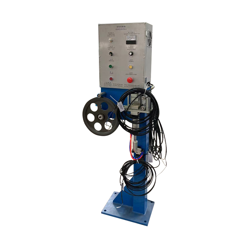
- 19 Product: Motorized Take-Up Equipment Machine
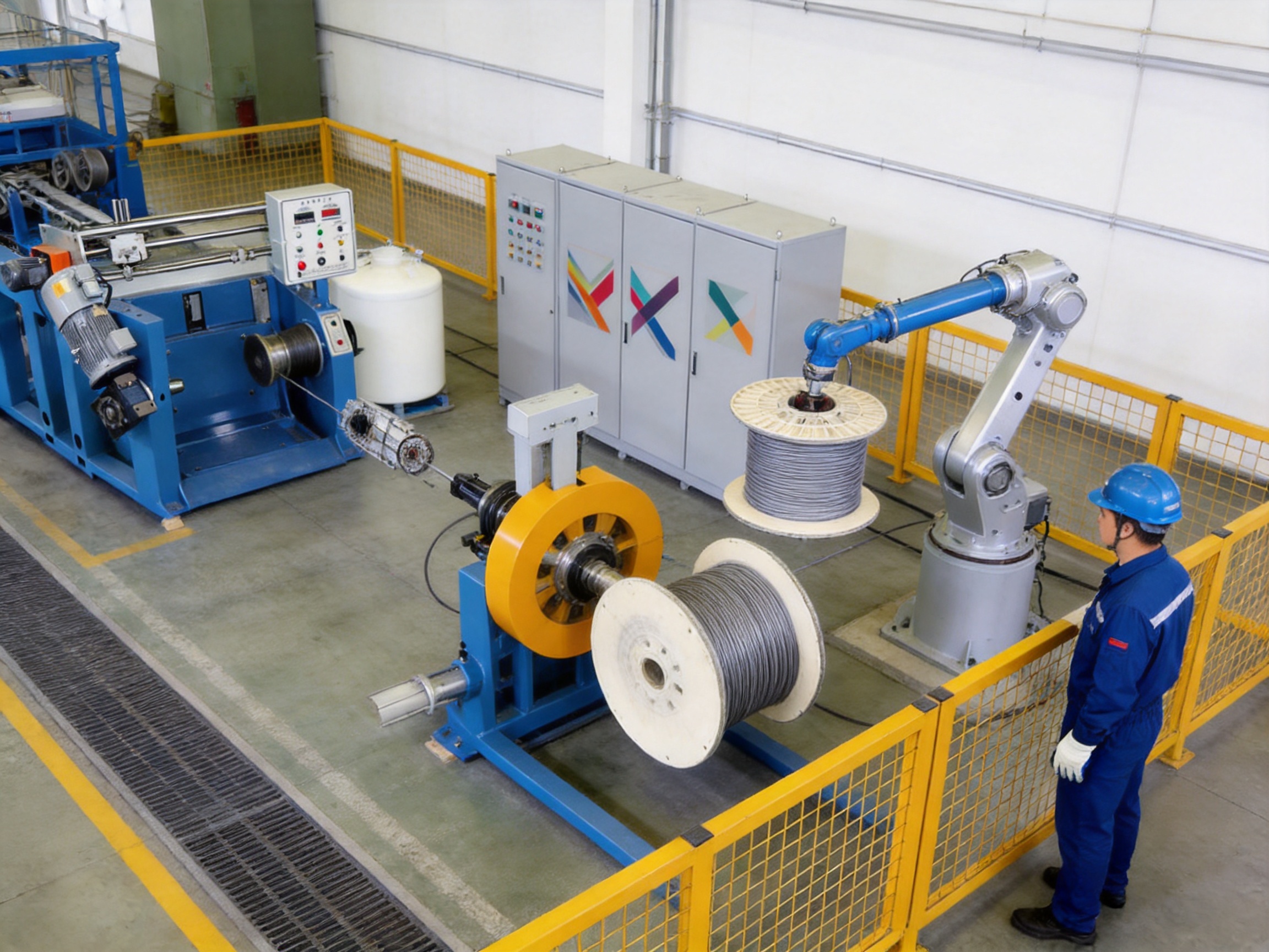
In modern wire and cable manufacturing, the take-up stage is far more than a simple cable collection process. It is the point at which the finished product must be wound under controlled tension, arranged in stable layers, protected from mechanical damage, and prepared for storage, transport, or the next production operation. A poorly designed take-up system can undermine the quality achieved by an otherwise advanced extrusion line. Uneven winding, excessive tension, crossed layers, spool eccentricity, and slow spool changes can generate substantial scrap and reduce overall production efficiency.
A motorized wire and cable take-up machine provides a coordinated solution to these challenges. Through electric drive technology, tension regulation, traversing control, spool handling, safety interlocks, and communication with upstream equipment, it automatically winds cables, wires, and flexible products onto reels or drums. The system is suitable for power cables, communication cables, automotive wires, building wires, data cables, and other continuous products manufactured through extrusion, insulation, sheathing, or coating processes.
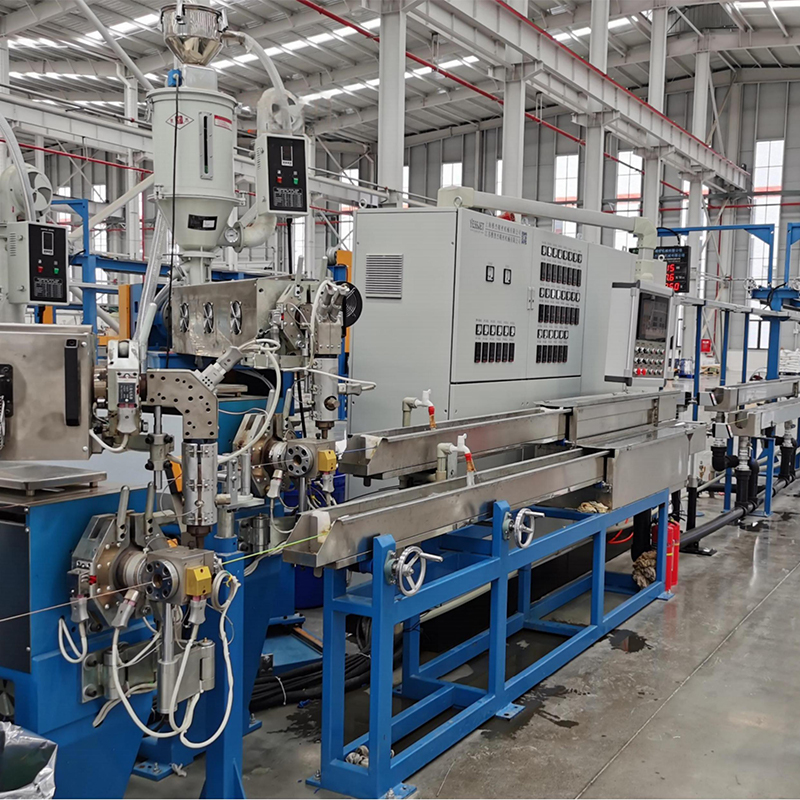
Shanghai Yessjet Precise Machinery Co., Ltd. develops and supplies motorized take-up equipment as part of a broader wire and cable machinery portfolio. Its manufacturing and engineering capabilities cover individual machines, auxiliary equipment, and complete wire and cable production line solutions. The company’s experience in integrating take-up equipment with extrusion lines enables customers to obtain not only a winding machine, but also a coordinated production system designed around speed matching, tension stability, spool specifications, control communication, and production requirements.
Why the Take-Up Stage Determines Final Cable Quality
During extrusion, the cable may pass through several carefully controlled processes, including conductor feeding, insulation or jacket extrusion, cooling, diameter measurement, spark testing, drying, and haul-off. At the end of the line, the take-up machine must receive the cable at production speed and wind it without changing its geometry or damaging its surface.
The take-up system must control several variables simultaneously. The winding torque must be sufficient to maintain a stable cable path, but not so high that the insulation is compressed or stretched. The rotational speed must increase or decrease as the spool diameter changes. The traverse mechanism must place each turn beside the previous turn with a suitable pitch. The spool must remain concentric and mechanically secure. During spool replacement, the line must either continue running through an accumulator or transition through a controlled speed sequence.
These requirements become more demanding as line speeds increase and cable diameters become larger. A small error in tension can be repeated thousands of times across a large spool. A minor mismatch between cable diameter and traverse pitch can create gaps, overlaps, or unstable layers. A slow changeover cycle can result in many meters of cable being downgraded or discarded. Therefore, the design of the motorized take-up machine has a direct effect on yield, product appearance, electrical performance, operator safety, and total cost per kilometer.
Unlike basic passive reels or manually operated winding devices, an automatic motorized take-up machine actively controls the winding process. It can adapt torque to the changing spool diameter, coordinate with the haul-off and extrusion line, manage the traverse movement, detect abnormal conditions, and stop automatically when the target length or spool capacity has been reached.
Working Principle of a Motorized Take-Up Machine
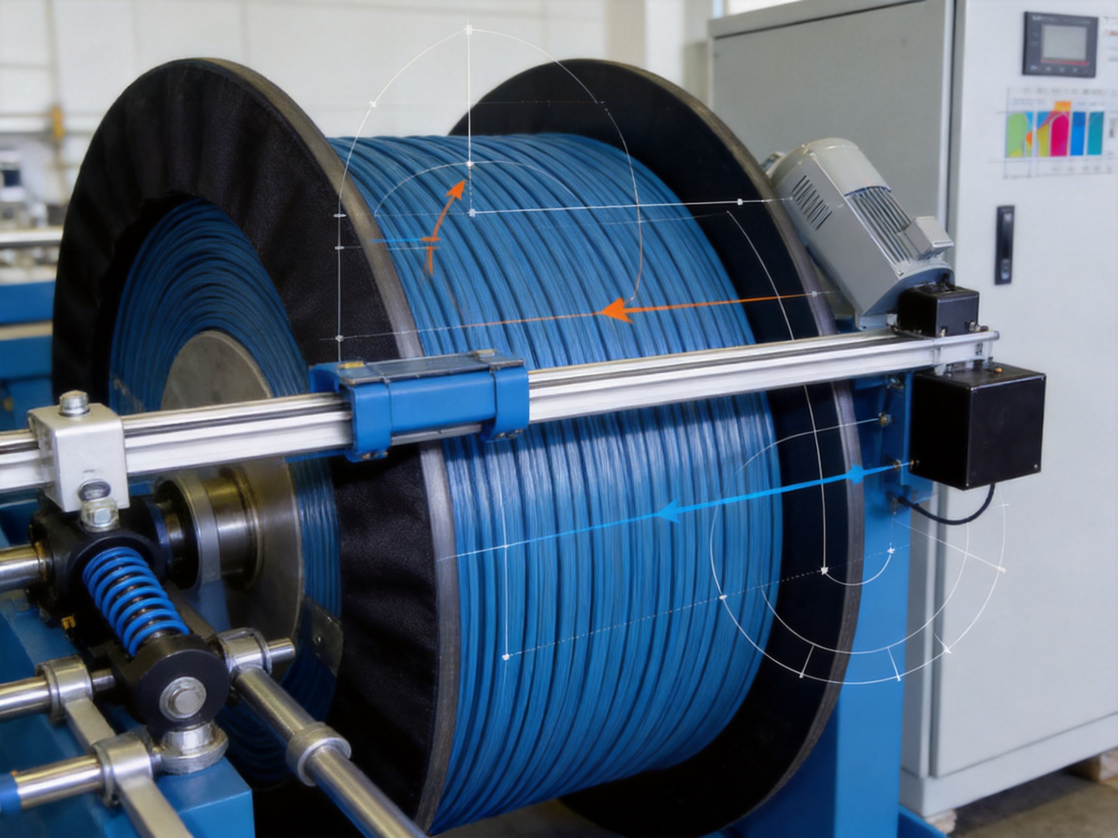
A typical motorized take-up system consists of a winding drive, spool support structure, traverse mechanism, tension control unit, meter counter, control cabinet, safety devices, and operator interface. Depending on the application, it may also include an accumulator, automatic cutter, spool clamping system, turret or carriage, lead attachment device, and communication interface for connection with the line master PLC.
The cable enters the take-up section through a guide path. A dancer roller or load cell measures or influences the tension condition. The cable then passes through the traversing guide, which moves laterally across the spool width. At the same time, the winding motor rotates the spool. The controller coordinates the rotation and traverse movement so that the cable is deposited in consistent layers.
As cable accumulates on the spool, the effective winding diameter increases. If the rotational speed remained constant, the surface speed of the cable would increase continuously and the cable would either be pulled tight or accumulate slack. To prevent this problem, the controller continuously adjusts the motor speed and torque. The take-up drive may operate in torque mode, speed mode, or a coordinated combination of both, depending on the line architecture and cable specification.
Torque control is especially useful when the upstream haul-off is the speed master. In this arrangement, the extrusion line determines the cable production speed, while the take-up motor supplies the controlled winding torque required to keep the cable path stable. The winding speed changes naturally with the spool diameter. A dancer position or tension sensor can provide a trim signal to adjust the torque setpoint without creating a conflict between two independent speed-control loops.
The system can also calculate the winding diameter from spool geometry, cable length, rotational speed, traverse movement, or a combination of these inputs. This information allows the machine to apply a programmed tension taper, compensate for the changing radius, control acceleration, and estimate remaining spool capacity.
Core Advantages Over Conventional Take-Up Equipment
Stable Tension Across the Full Spool Build
Consistent tension is one of the most important advantages of a properly engineered motorized take-up machine. Excessive tension can stretch conductors, deform insulation, compress cable jackets, or alter the geometry of flexible products. Insufficient tension can produce loose coils, unstable layers, cable loops, and tangling during later payout.
Advanced motorized take-up equipment uses a combination of motor torque control, dancer feedback, load cell measurement, acceleration management, and recipe-based parameters. This allows the system to respond to changes in winding diameter and line speed while maintaining the selected tension range.
For large cable spools, constant tension is not always the correct strategy. The inner layers are wound first and are later subjected to the radial pressure generated by all the layers above them. If the same tension is maintained from the empty core to the full spool, the compressive force on the inner cable layers can become excessive. This may cause jacket deformation, increased capacitance, or possible dielectric weakness that is not visible from the outside.
Taper tension winding solves this problem by gradually reducing the winding tension as the spool diameter increases. The starting tension is applied near the core, while the tension at the full spool is reduced according to a linear or curved taper profile. For many PVC-insulated power cable applications, the full-diameter tension may be set at approximately 60% to 75% of the starting tension, although the correct value must be determined from the cable construction, jacket modulus, spool geometry, and allowable compressive stress.
Accurate Traverse Pitch and Layer Formation
The traverse system determines how the cable is distributed across the spool width. A suitable pitch places adjacent turns close enough to create a compact layer without allowing them to overlap or damage one another. If the pitch is too tight, the cable may dig into neighboring turns. If the pitch is too wide, gaps can form and upper layers may fall into the spaces between lower turns.
The theoretically correct single-layer pitch is generally based on the cable outer diameter plus a small clearance allowance. For cables with stable dimensions, the machine can use a fixed pitch derived from the maximum allowable cable diameter. For cables with wider diameter variation, a laser gauge or other measurement device can provide real-time diameter information, allowing the traverse pitch to be updated during production.
The machine’s controller can store different pitch values, acceleration profiles, reversal settings, and tension recipes for different cable specifications. This is more efficient than adjusting mechanical components manually for every product changeover. It also reduces the risk of operator error and improves repeatability between production batches.
Reduced Scrap During Spool Changes
Spool changing is a major source of material loss on conventional take-up systems. When a full spool is removed and an empty spool is installed, the upstream line may continue producing cable. If the line must be stopped, production efficiency decreases. If the line continues operating without adequate buffering, cable may accumulate on the floor, become damaged, or require downgrading.
An automatic take-up machine can reduce this loss through a coordinated change sequence. The sequence may include full-spool detection, accumulator activation, cable cutting, tail securing, spool indexing, empty-spool positioning, cable lead attachment, and winding acceleration. Each step is managed through programmable logic and interlocking signals.
Turret-style take-up equipment can complete spool indexing much faster than a single-position machine that depends on forklift exchange. Servo-driven acceleration also allows the new spool to reach stable winding conditions quickly. The result is shorter changeover time and a smaller amount of cable produced outside the ideal winding condition.
For example, at a line speed of 200 meters per minute, a 30-second changeover may expose approximately 100 meters of cable to potentially unstable or off-specification conditions. If the changeover time is reduced to eight seconds, the corresponding length falls to approximately 27 meters. This represents a significant reduction in scrap, particularly on high-output lines with frequent spool changes.
Improved Operator Safety
Manual handling of large loaded spools exposes operators to lifting hazards, pinch points, unexpected rotation, and cable recoil. A motorized take-up machine can incorporate guarded rotating components, emergency stops, safety switches, spool locking devices, controlled acceleration, and automatic fault shutdown.
When a spool is not correctly clamped, when the cable breaks, when the dancer moves outside its operating range, or when the safety guard is opened, the machine can stop or enter a safe operating state. These functions reduce the need for operators to work near moving components while the machine is running.
Lower Labor Requirements and Higher Repeatability
Conventional winding often depends on operators to monitor cable tension, adjust traverse movement, stop the line, cut the cable, tie the tail, exchange the spool, and restart production. Results can vary according to operator experience and attention. Automatic equipment transfers these repetitive functions to a controlled sequence.
Operators can focus on process supervision, quality verification, spool inspection, and material handling rather than continuously correcting winding behavior. Recipe storage also allows the same cable specification to be produced with consistent machine parameters across shifts and production days.
Tension Control Architecture
Dancer-Based Tension Control
A dancer system uses a spring-loaded or pneumatically loaded roller positioned in the cable path. The position of the dancer reflects changes in cable tension and provides a buffering function. When the upstream line speed or winding speed changes temporarily, the dancer can move within its travel range and absorb part of the transient.
The main advantage of dancer control is its combination of indirect tension feedback and mechanical accumulation. It is often suitable for extrusion lines where speed changes occur during startup, product transition, or spool replacement. It can also be easier to commission than a high-bandwidth load cell system.
However, dancer position is not a direct measurement of tension at the winding point. Friction in guide rollers, eyelets, and cable paths can create a difference between the force measured at the dancer and the actual force applied to the spool. This effect is more significant for large, stiff cables that resist bending.
Load Cell-Based Tension Control
A load cell system measures force directly through an instrumented guide roller, fixed guide pin, or other tension-measuring assembly. It provides an electrical signal proportional to the cable force at the measurement location. Because the measurement is direct, load cell control can provide more precise information for high-speed winding and applications requiring rapid correction of tension transients.
The trade-off is that load cells do not provide the same inherent buffering as dancer systems. The control loop must respond quickly to disturbances, and poor tuning may cause oscillation. Load cells also require careful installation, protection from mechanical shock, and periodic calibration. Temperature changes, zero drift, and long-term mechanical fatigue must be considered in the maintenance plan.
Selecting the Appropriate System
The choice between dancer-based and load cell-based tension control depends on cable construction, production speed, allowable tension variation, line layout, and the desired level of automation. A dancer system may be preferable for lines requiring buffering and smooth transitions. A load cell system may be preferable for high-speed products where direct tension measurement and rapid correction are more important.
In some applications, both systems can be integrated. A dancer may provide accumulation and speed-transient absorption, while a load cell supplies direct tension feedback. The control architecture must be designed carefully so that the signals complement one another instead of creating conflicting correction commands.
Mechanical Compatibility with Winding Spools
The take-up machine cannot produce a stable spool if the spool itself is mechanically unsuitable. Many cable manufacturers use spool inventories supplied by different vendors over a long period. Differences in bore diameter, keyway dimensions, flange runout, and structural capacity may be small but still significant during high-speed winding.
A spool bore that is only slightly larger than the shaft can permit eccentric rotation. This eccentricity creates a once-per-revolution tension ripple that cannot be fully corrected through software because the disturbance originates from the mechanical interface. A loose keyway can also allow micro-slip during acceleration and deceleration, creating localized tension spikes.
Before production use, spool batches should be checked for bore diameter, keyway fit, flange runout, and load rating. Precision applications generally require a close and repeatable fit between the shaft and spool interface. Spools with excessive variation may require adapter sleeves, although adapters introduce additional components that must be aligned and maintained.
| Spool Parameter | Recommended Verification | Potential Consequence of Poor Compatibility |
| Bore diameter | Measure with a calibrated bore gauge and compare with shaft tolerance | Eccentric rotation and periodic tension fluctuation |
| Keyway width and depth | Check against the shaft key and specified fit class | Micro-slip, shock loading, and inaccurate winding |
| Flange runout | Inspect on a reference mandrel with a dial indicator | Uneven layers and flange-side edge beads |
| Gross load capacity | Compare rated capacity with spool tare weight and cable fill weight | Flange deformation, bearing overload, and safety risk |
| Core and flange dimensions | Confirm against the machine recipe and traverse range | Incorrect pitch, limited capacity, or cable contact with the flange |
For reference, flange runout exceeding approximately 0.5 millimeters per 300 millimeters of flange radius may create visible winding defects, particularly when the cable is sensitive to layer displacement. The maximum fill weight should also include a suitable safety factor. A commonly applied engineering approach is to maintain a minimum safety factor of 1.5 between the calculated loaded condition and the spool’s rated gross capacity.
Advanced Control Functions
Recipe-Based Production Management
A recipe system allows operators to store and recall winding parameters for each cable type. A typical recipe may include cable diameter, spool dimensions, target length, starting tension, taper ratio, traverse pitch, acceleration and deceleration limits, reversal behavior, line communication settings, and spool-change timing.
Recipe management improves changeover efficiency and protects production knowledge. Instead of relying on handwritten notes or operator memory, the machine uses a repeatable parameter set. Access permissions can be assigned so that experienced engineers define the parameters while operators select approved recipes.
Diameter Compensation
As the spool fills, the winding radius changes continuously. The controller can estimate this change using cable length, rotational speed, spool dimensions, and traverse information. When higher precision is required, diameter feedback can be supported by an external measurement device or calculated from the relationship between line speed and spool rotation.
Accurate diameter compensation helps maintain stable surface speed and prevents the cable from being pulled or pushed during winding. It also supports taper tension control and improves the accuracy of target-length calculations.
Automatic Stop and Fault Detection
The machine can be configured to stop automatically when the target length is reached, the spool reaches its permitted fill diameter, the cable breaks, the dancer leaves its operating range, or a guard is opened. Additional monitoring may include motor overload, drive fault, communication failure, abnormal vibration, spool locking status, and emergency-stop activation.
These functions protect the cable and the equipment. They also help operators identify the cause of a problem quickly instead of discovering it later during spool inspection.
Communication with the Extrusion Line
A take-up machine must communicate clearly with the upstream extrusion line. Typical signals include line running status, speed reference, accumulator level, spool-full status, changeover request, cable-break signal, take-up-ready status, and emergency-stop interlock.
For retrofit projects, the control architecture must be reviewed before installation. If both the haul-off and take-up attempt to control cable speed independently, they may respond in opposite directions and create oscillation. The standard solution is to keep the haul-off as the speed master and configure the take-up drive in torque-control mode. The dancer signal then trims the torque command rather than competing with the haul-off speed loop.
Shanghai Yessjet Precise Machinery Co., Ltd. approaches retrofit integration by reviewing the existing line’s haul-off drive, communication protocol, available input and output points, safety interlocks, and accumulator arrangement. This engineering audit helps define the control relationship before commissioning begins. It also reduces the risk of discovering loop interaction problems only after the line has entered production.
Manufacturing Strengths and Engineering Process
The performance of a motorized take-up machine depends not only on the selected motor or controller. Mechanical rigidity, machining accuracy, electrical assembly, software logic, component matching, and final testing all influence the finished result. A strong manufacturer therefore needs capabilities across mechanical design, automation, fabrication, integration, and after-sales support.
Application-Based Design
Yessjet’s equipment development is based on the cable application rather than a one-size-fits-all machine concept. Product parameters such as cable diameter, insulation material, maximum line speed, spool size, cable weight, winding length, tension range, and expected changeover frequency influence the machine configuration.
For light building wire, the system may prioritize compact design, high traverse accuracy, and rapid speed response. For large power cables, the design must emphasize shaft strength, bearing capacity, braking performance, spool locking, and controlled tension taper. For flexible automotive or communication cables, smooth handling and precise layer placement may be the most important considerations.
Mechanical Fabrication and Assembly
The frame and spool support structure must resist vibration and deflection while the cable is being wound. The shaft, bearing arrangement, clamping devices, and traverse assembly must be aligned accurately. A rigid structure helps prevent unwanted movement that would otherwise appear as layer variation or tension fluctuation.
Mechanical assembly should include alignment checks for the winding shaft, traverse guide, cable entry path, and spool flanges. The cable path should avoid unnecessary friction and sharp bending. Contact surfaces must be selected to protect cable jackets and insulation, particularly when the machine handles finished products with sensitive surfaces.
Drive and Control Integration
The motor, reducer, inverter or servo drive, tension controller, sensors, and PLC must be selected as a coordinated system. A motor with sufficient rated power may still perform poorly if its low-speed torque characteristics, braking response, or inertia matching are unsuitable for the application.
Yessjet’s wire and cable machinery experience supports the integration of take-up equipment with extrusion lines, pay-off units, cooling systems, spark testers, meter counters, and other auxiliary equipment. This broad system knowledge is valuable when a customer requires a complete line rather than an isolated winding unit.
Testing and Commissioning
A professional manufacturing process should include electrical inspection, mechanical function testing, drive commissioning, safety verification, dry running, and cable trial production. During trial operation, the machine should be checked at different winding diameters, line speeds, tensions, and traverse settings.
Testing should verify that the spool rotates smoothly, the traverse reverses without excessive impact, the dancer or load cell signal remains stable, the tension follows the selected recipe, and the machine responds correctly to cable breaks and emergency-stop commands. Spool change sequences should be tested under realistic operating conditions rather than only at low speed.
Final acceptance can include inspection of cable appearance, layer stability, spool density, target length, tension consistency, and changeover scrap. A structured test process gives customers greater confidence that the machine will perform reliably after installation.
Application Areas
Power Cable Production
Power cables often require large spools, high load capacity, and carefully controlled tension. The take-up system must prevent excessive compression of insulation and maintain stable layers throughout the spool build. Taper tension, robust shaft construction, and accurate spool alignment are particularly important.
Building Wire and Single-Core Cable
Building wire usually requires consistent pitch, high production speed, and compact but repeatable winding. Because the outer diameter is often relatively stable, the traverse system can use a defined pitch based on the maximum production diameter and a suitable clearance allowance.
Flexible Multi-Core Cable
Flexible cables may have wider outer-diameter variation and can be more sensitive to compression, bending, and surface contact. A motorized take-up machine can use lower winding tension, a suitable taper profile, and, where required, real-time diameter measurement to maintain layer quality.
Automotive and Communication Cable
Automotive and data cables often require careful surface protection and consistent handling. Small changes in tension or bending radius can influence conductor position, shielding, or insulation appearance. Precise guides, low-friction contact surfaces, sensitive feedback, and controlled acceleration are useful for these applications.
Mining and Port Machinery Cables
Heavy-duty cables used in mining and port machinery are generally larger, heavier, and more mechanically demanding. Their take-up equipment must be designed around high spool weight, strong shaft support, controlled braking, and safe handling. The machine may also need to work with specialized reels and long cable lengths.
Comparison with Conventional and Lower-Cost Alternatives
A manual or lightly motorized reel may have a lower purchase price, but its total cost can be higher when labor, scrap, quality variation, and downtime are considered. Manual systems depend heavily on operator intervention and may not maintain consistent tension as the spool fills.
Some basic motorized systems use a fixed-speed motor without adequate diameter compensation. These machines may work for limited cable sizes, but they become unstable when the spool radius changes substantially. They may also lack programmable taper tension, precise traverse control, or coordinated spool change functions.
Higher-quality automatic take-up equipment offers several competitive advantages:
- Closed-loop or controlled tension adjustment instead of simple fixed-speed winding
- Programmable taper tension for large spool builds
- Recipe-based traverse pitch and cable-specific winding parameters
- Torque and speed coordination with upstream haul-off equipment
- Automatic stop, spool-full detection, and fault protection
- Reduced spool-change time and lower cable scrap
- Compatibility evaluation for different spool dimensions and load ratings
- Integration support for complete extrusion lines and retrofit projects
- Improved operator safety through guarding, interlocks, and controlled motion
- More consistent spool quality between operators and production shifts
The most important comparison should not be limited to machine purchase price. Customers should evaluate usable production speed, cable yield, average spool quality, maintenance access, control flexibility, safety features, commissioning support, and the manufacturer’s ability to provide future technical assistance.
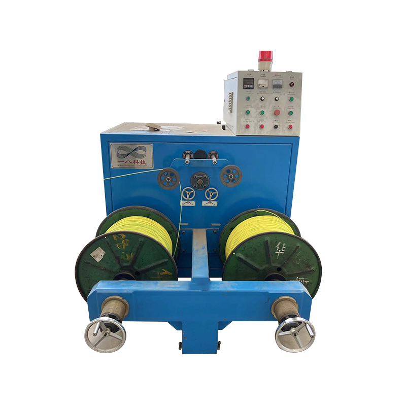
Motorized Take-Up Equipment Machine
How to Specify the Correct Equipment
Before selecting a motorized take-up machine, the customer should prepare a complete technical specification. Important information includes the minimum and maximum cable diameter, cable construction, insulation or jacket material, line speed range, target winding length, spool dimensions, maximum loaded spool weight, desired tension range, and available factory space.
The customer should also identify whether the line requires fixed-position winding, carriage exchange, or turret-style automatic spool changing. If continuous production is required, accumulator capacity and changeover timing must be calculated together with the take-up configuration.
Control information is equally important. The supplier should understand the existing haul-off drive, PLC platform, communication protocol, encoder signals, dancer arrangement, available I/O, emergency-stop circuit, and operator interface requirements. For a new production line, these elements can be designed together. For a retrofit, they must be reviewed carefully to avoid control-loop conflicts.
Key Technical Questions for the Supplier
Can the machine maintain stable tension from an empty core to a full spool? Does it support taper tension profiles? How is winding diameter calculated? Can traverse pitch be changed through a recipe? What happens if cable diameter varies during production? How long does the spool change sequence take? Can the system communicate with the existing line PLC? What spool tolerances are acceptable? How are cable breaks and emergency conditions handled?
A capable supplier should answer these questions with engineering details rather than general promises. The proposed machine should be matched to the actual product and line conditions. A demonstration using a representative cable and spool can provide useful evidence of winding quality and control performance.
Installation, Commissioning, and Operator Training
Installation begins with checking the foundation, machine orientation, cable entry height, spool handling space, electrical supply, compressed air requirements if applicable, and communication connections. The machine should be positioned so that operators can safely load and unload spools while maintaining clear access to emergency devices.
After mechanical installation, the shaft alignment, spool clamping, traverse position, sensor calibration, motor direction, and safety circuits should be checked. Control parameters should be entered according to the approved cable recipes. The first production trial should begin at a controlled speed, allowing the commissioning team to verify tension, pitch, acceleration, and layer formation before operating at the maximum line speed.
Operator training should cover recipe selection, spool inspection, cable threading, dancer or load cell checks, alarm interpretation, emergency-stop procedures, manual recovery, spool-change operation, and routine cleaning. Maintenance personnel should also be trained in lubrication, sensor inspection, drive fault diagnosis, and mechanical alignment checks.
Maintenance and Long-Term Reliability
Routine maintenance helps preserve winding accuracy and reduce unplanned downtime. The shaft, bearings, reducer, traverse rails, guide rollers, cable-contact surfaces, sensors, and electrical cabinet should be inspected according to a defined schedule.
Guide rollers must remain clean and rotate freely. Dirt or damaged surfaces can increase friction and mark cable jackets. Dancer rollers should move smoothly through their full travel range. Load cells should be protected from impact and periodically checked for zero drift. The traverse mechanism should be inspected for backlash, unusual noise, and excessive clearance.
Spool clamping components should be checked for wear and correct locking force. A loose spool can create eccentric rotation, while excessive clamping force may damage the spool or interfere with removal. Drive parameters should be backed up so that approved recipes can be restored after controller replacement or maintenance.
Maintenance records should include fault events, cable breaks, tension deviations, spool damage, bearing temperature, and changeover performance. This information helps identify recurring issues and supports continuous process improvement.
Economic Benefits of Automatic Take-Up Technology
The financial value of a motorized take-up machine comes from several sources. Reduced scrap is often the most immediate benefit. Stable tension and accurate traverse movement reduce cable damage and make more of the produced length saleable. Faster spool changes reduce the amount of cable produced during transition conditions.
Labor savings are also important. Automatic winding reduces the number of operators required to monitor the process and perform manual spool-handling tasks. Consistent machine operation can reduce rework and customer complaints caused by poor spool quality.
Higher equipment availability contributes to the overall return on investment. A robust machine with accessible components, clear diagnostics, and reliable safety functions can reduce downtime compared with equipment that requires frequent manual correction. Integration with the line master control system also makes production planning and fault recovery more efficient.
When evaluating investment, manufacturers should calculate the cost per spool change, the average scrap length, the number of changes per shift, the labor time per change, and the cost of rejected or downgraded cable. These figures often demonstrate that a more advanced automatic system provides a lower total cost of ownership even when its initial purchase price is higher.
Quality and Process Control Recommendations
For each cable specification, the production team should establish approved values for starting tension, full-spool tension, taper ratio, traverse pitch, reversal profile, acceleration, deceleration, and maximum winding diameter. These values should be verified through trial production and then protected within the recipe management system.
Quality checks should include visual inspection of the spool, measurement of layer uniformity, verification of cable length, examination of cable surface condition, and confirmation that the spool can be used safely on the customer’s payout equipment. For sensitive cables, electrical tests such as capacitance measurement, insulation resistance, or dielectric testing may be used to verify that winding pressure has not affected cable performance.
Process data can be reviewed after production. Trends in tension, motor torque, dancer position, line speed, spool diameter, and changeover time may reveal developing problems before they become serious. A sudden increase in torque variation could indicate a damaged spool, bearing issue, guide friction, or cable diameter instability.
Q&A: Motorized Wire and Cable Take-Up Equipment
What is a motorized take-up machine?
A motorized take-up machine is an electrically driven device that winds wire, cable, or filament onto a spool. It controls winding torque, rotation, traverse movement, and often communicates with the upstream production line to maintain stable cable tension and organized layers.
What is the difference between a pay-off and a take-up machine?
A pay-off machine releases cable or wire from a reel into the production line. A take-up machine receives the finished product from the line and winds it onto a spool. In a complete wire and cable production system, the pay-off is generally located near the beginning of the line, while the take-up is installed at the downstream end.
Why is constant tension not always recommended?
Constant tension can apply excessive compressive force to the inner layers of a large spool because every outer layer adds pressure to the cable below it. Taper tension reduces the winding force as the spool diameter increases, helping protect insulation and jacket materials.
What is taper tension?
Taper tension is a programmed reduction in winding tension as the spool builds. The reduction may follow a linear or curved profile. The correct taper ratio depends on cable construction, jacket properties, spool geometry, winding diameter, and acceptable compressive stress.
How is traverse pitch selected?
Traverse pitch is usually based on the cable outer diameter plus a small clearance allowance. The maximum permitted cable diameter is often used for dimensionally stable products. If the diameter varies significantly, real-time measurement can be used to adjust the pitch during production.
Which tension feedback system is better: dancer or load cell?
Neither system is universally better. A dancer provides buffering and is useful for absorbing speed transients. A load cell provides direct tension measurement and may be better for high-speed applications requiring rapid response. The correct selection depends on the cable, line speed, control architecture, and required tension accuracy.
Can the machine be installed on an existing extrusion line?
Yes. A retrofit is possible, but the existing haul-off drive, PLC, communication protocol, accumulator, available I/O, safety circuit, and control philosophy must be reviewed. In many retrofit applications, the haul-off remains the speed master and the take-up operates in torque-control mode to prevent control-loop conflict.
How can spool-change scrap be reduced?
Scrap can be reduced by using an accumulator with appropriate capacity, fast full-spool detection, automatic cutting and tail securing, turret or carriage exchange, servo-driven acceleration, and a well-coordinated PLC handshake between the take-up and extrusion line.
What spool information should be provided to the machine supplier?
The supplier should receive the spool bore diameter, shaft interface, keyway dimensions, flange diameter and width, core diameter, maximum loaded weight, flange runout, target winding length, and any special handling requirements. Accurate spool data is necessary for safe and stable machine design.
What cable types can be handled?
Depending on the selected configuration, motorized take-up equipment can handle building wire, power cable, communication cable, automotive wire, flexible multi-core cable, coaxial cable, armored cable, mining cable, and other continuous products. The machine must be matched to the cable diameter, weight, flexibility, surface material, and production speed.
What support can a machinery manufacturer provide?
Support may include application assessment, machine configuration, control-system design, spool compatibility review, manufacturing, factory testing, installation guidance, commissioning, operator training, spare parts, and technical assistance. A manufacturer with experience in complete wire and cable production lines can also help coordinate the take-up with upstream and downstream equipment.
Why Choose an Integrated Machinery Partner
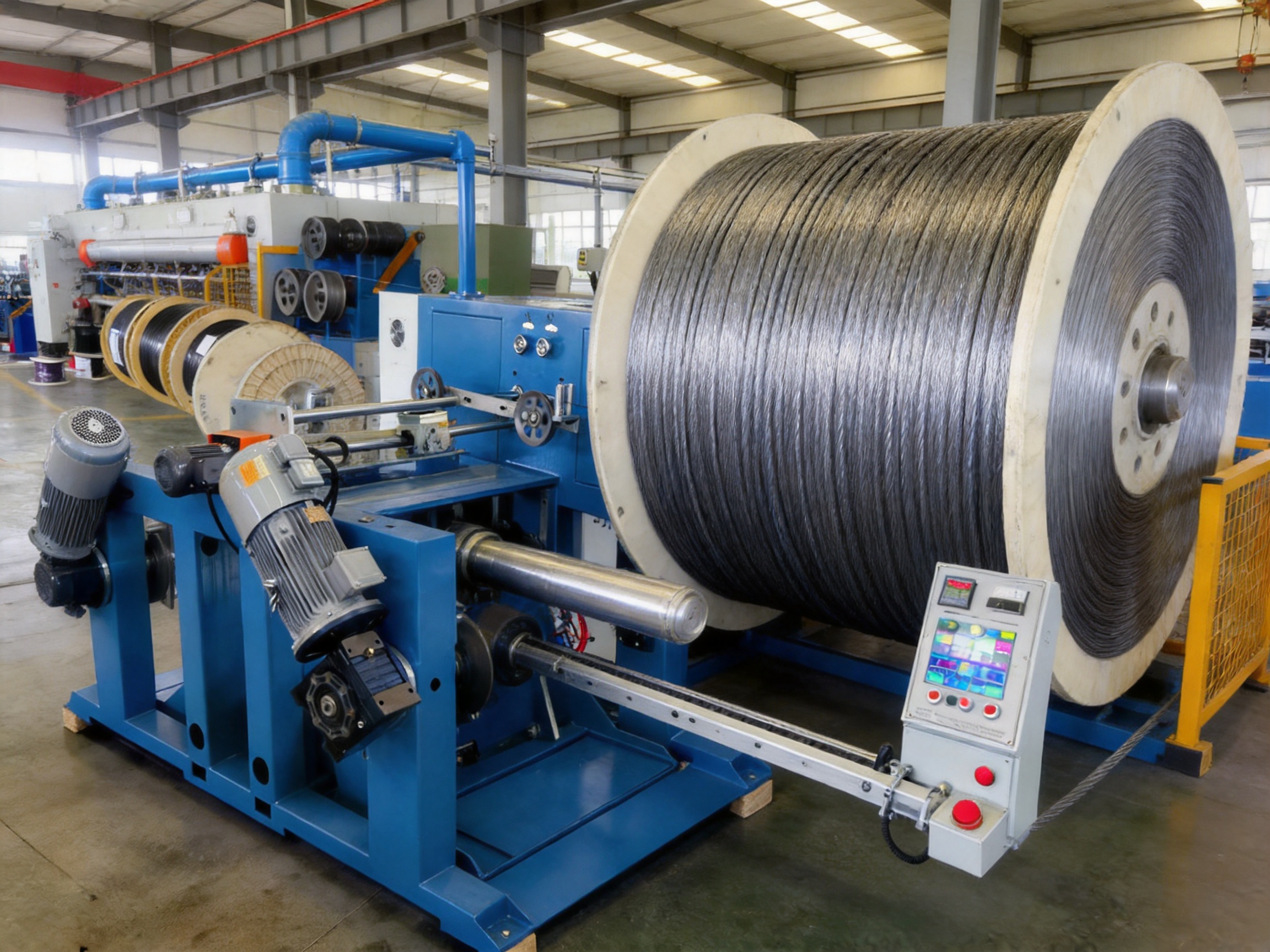
A take-up machine is most effective when its mechanical and control functions are designed as part of the complete production process. Purchasing isolated equipment from multiple suppliers may create compatibility problems involving line speed, communication signals, tension feedback, spool dimensions, and safety interlocks.
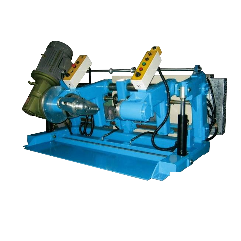
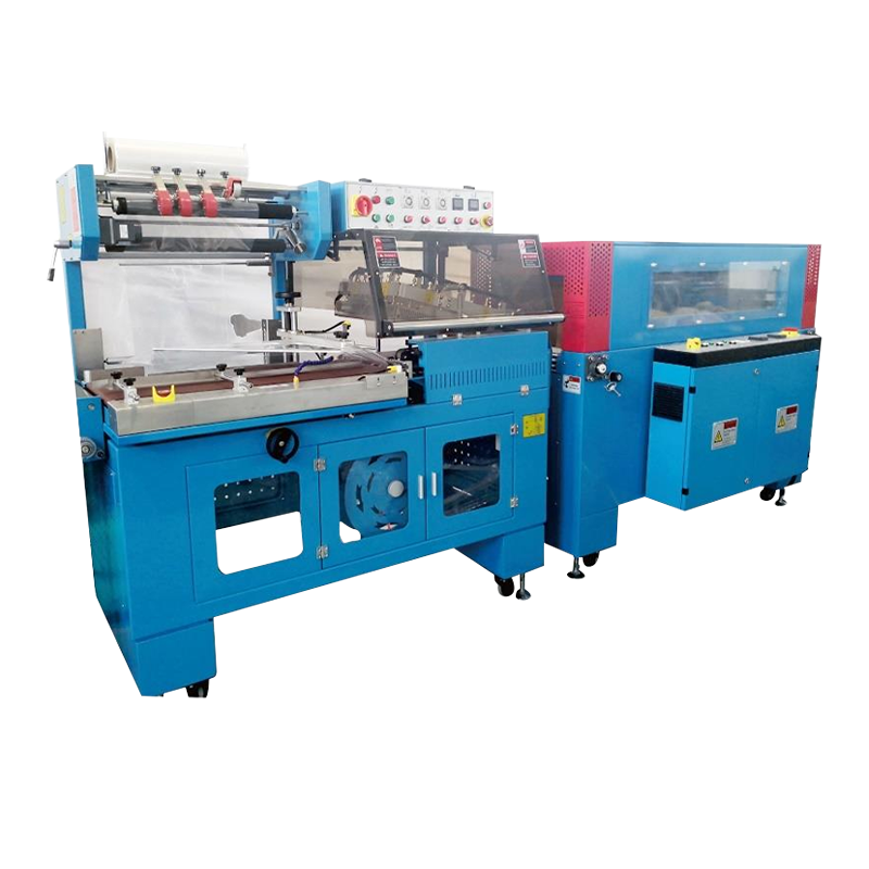
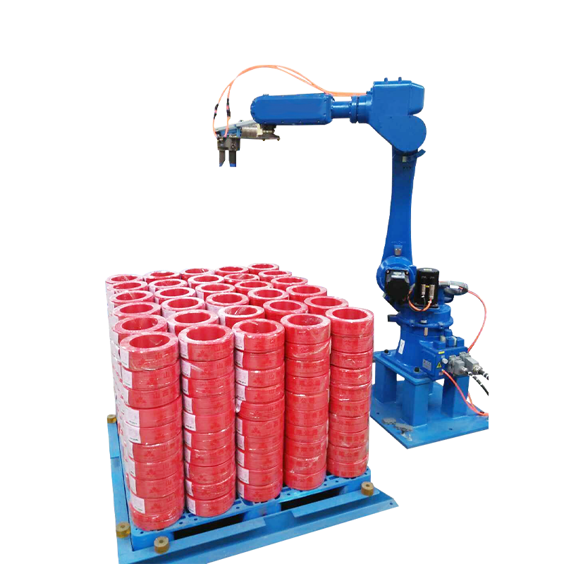
Shanghai Yessjet Precise Machinery Co., Ltd. offers experience in wire and cable machinery, cable extrusion equipment, pay-off systems, take-up systems, coiling machines, automatic coiling and packaging equipment, accessory equipment, and intelligent robot stacking solutions. This wider product scope allows the company to understand the complete material flow from conductor feeding to finished spool handling.
The company was established in Shanghai in 2002 with investment from Taiwan and expanded through Jiangsu Yessjet Precise Machinery Co., Ltd. in Yixing, Wuxi, in 2017. Its engineering background supports customized equipment development for different cable products, factory layouts, production capacities, and automation levels.
For customers purchasing a motorized take-up machine, this integrated capability can simplify project coordination. The supplier can evaluate the line speed, cable characteristics, spool standards, control requirements, and future automation plans before recommending the machine configuration. This reduces the risk of selecting equipment that performs well as a standalone unit but does not integrate properly into the production line.
Conclusion
A motorized wire and cable take-up machine is a critical production asset that influences winding quality, material yield, labor requirements, line stability, and operator safety. The best equipment does more than rotate a spool. It manages changing winding diameter, maintains appropriate tension, applies accurate traverse pitch, performs controlled spool changes, communicates with the extrusion line, and protects the cable from mechanical damage.
Advanced functions such as taper tension, dancer or load cell feedback, recipe management, automatic diameter compensation, servo acceleration, fault detection, and spool compatibility control provide clear advantages over conventional manual or fixed-speed systems. These functions are especially valuable for large cable spools, high-speed extrusion lines, sensitive insulation materials, and production environments where scrap reduction is a major priority.
Yessjet combines wire and cable machinery experience with mechanical fabrication, automation integration, application engineering, and complete line capability. Its motorized take-up equipment can be configured for different cable types, spool sizes, production speeds, control architectures, and automation requirements. By treating the take-up machine as an integrated part of the cable production process, manufacturers can improve spool stability, reduce changeover waste, simplify operation, and achieve more consistent finished-product quality.
For technical consultation, customers may contact Shanghai Yessjet Precise Machinery Co., Ltd. through its sales team to discuss cable specifications, spool standards, line integration, and customized motorized take-up requirements.
References
1. Industrial cable winding and reel-handling engineering practices.
2. Principles of tension control for continuous web, wire, and cable processing.
3. Guidelines for spool geometry, flange runout, shaft interfaces, and mechanical load ratings.
4. Variable-frequency drive and servo-drive applications in continuous production machinery.
5. Programmable logic controller architecture for extrusion line synchronization and automatic spool changing.
6. Industrial safety principles for rotating machinery, guarding, emergency stops, and automatic material handling.
7. Quality-control methods for cable extrusion, insulation protection, winding density, and finished-spool inspection.
8. Shanghai Yessjet Precise Machinery Co., Ltd. technical materials for wire and cable extrusion, take-up, pay-off, coiling, packaging, and automated handling equipment.
Company: Shanghai Yessjet Precise Machinery Co., Ltd.
Address: No. 27, Youth Farm, Fengyi Village, Guanlin Town, Yixing City, Jiangsu Province, China.
Email: sales@yessjet.com
Telephone: +86-0510-87258118